Step By Step Motorcycle Frame Jig Assembly Tutorial!

The following motorcycle frame jig assembly directions shows you how to build a motorcycle frame jig based upon the plans that are available here. You should reference these plans in order to build it properly.
If you would like the printed book form on how to build a frame jig for a softail or hardtail chopper let us know. We are considering offering a printed version of it.
However, this version is very good and highly detailed.
It's so detailed in fact that a beginner with metalwork experience and metal shop (welding) safety training can enjoy the build, step by step.
Motorcycle Frame Jig Assembly Guide:
Machinery and Tools Required:
1. Chop saw or Angle grinder.
2. Universal or CNC milling machine (recommended).
3. Plasma cutter (recommended).
4. MIG, TIG or Arc Welding.
5. Drill press.
6. Fitter’s vise.
7. Hammer, wrench set, tape measure, caliper.
8. Drill set.
Materials Required:
1. Mild steel square tube – 2’’ x 2’’ (235 ft).
2. Angle iron – 2 x 3’’ (156 in).
3. Mild steel sheet – 1/4’’ thickness (257 in2).
4. 1 ¼’’ tube (30 in); 1 ½’’ tube (62 in).
5. 3/8’’ threaded rod (32 in).
6. (4) HBOLT 5/8x45’’.
7. (16) HBOLT 1/4-20x3.25.
8. (14) HBOLT 3/8-16x3.5.
9. (4) 5/8’’ WASHER-NUT.
10. (4) 5/8’’ NUT.
11. (16) 1/4-20’’ NUT.
12. (14) 3/8-16’’ NUT.
13. (4) 5/8 WASHER.
14. (52) 3/8 WASHER.
15. (1) Retaining splint 1.
16. (1) Locking sleeve (Available from MCMASTER/GRAINER).
17. (10) Tube end cap (Available from various suppliers: 8020.net).
18. (4) Caster wheel CPS 40156TZ-ROI81(KK)TB.
1. Assembling The Left Stand.
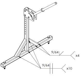 Fig. 1.1 Left stand assembly welding plan.
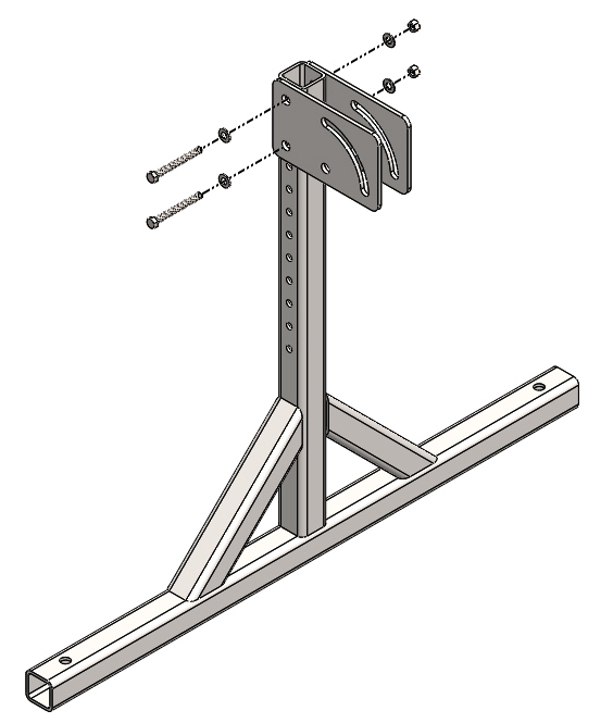
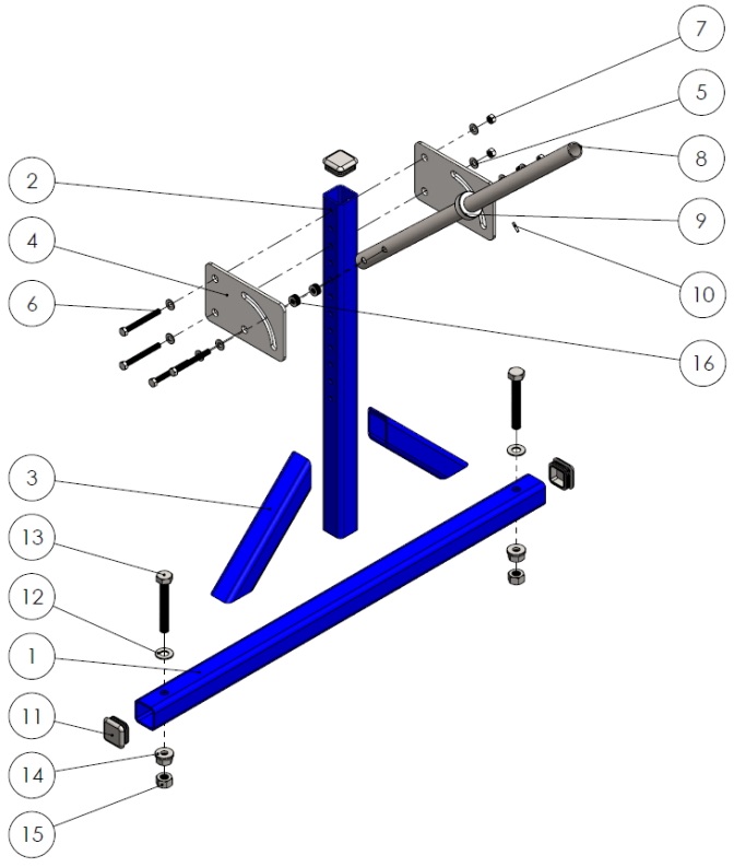 Fig. 1.2 Left stand assembly montage plan.
Parts:
1. Square tube 2 x 2 x 40’’.
2. Square tube 2 x 2 x 29.5’’.
3. Square tube 2 x 2 x 12’’ with 45º miter cut both ends.
4. Steering head plate 5 x 8 x ¼’’.
5. 3/8’’ Washer.
6. 3/8’’ x 3.5’’ Hex bolt.
7. 3/8’’ Nut.
8. Steering head shaft 1 ¼ x 30’’ .
9. Locking sleeve.
10. Retaining splint.
11. Square tube end cap.
12. 5/8’’ Washer.
13. 5/8’’ x 4.5’’ Bolt.
14. 5/8’’ Washer-nut.
15. 5/8’’ Nut.
16. 6 x 3/8’’ Set of washers.
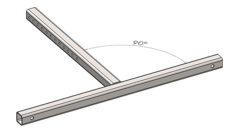
Step 1: Cut two pieces of 2 x 2 x 29.5’’ and 2 x 2 x 40’’ long square tube using an angle grinder. Take the 2 x 2 x 29.5’’ and drill 12 x 0.4 holes according to the drawing and then drill two 5/8’’ holes in 40’’ long piece. Take one piece of 29.5’’ and one piece of 40’’ long square tube and position them on a flat work surface as shown on the next figure. Make sure the 90º angle is accurate and complete the welds according to the welding plan (Fig. 1.1).
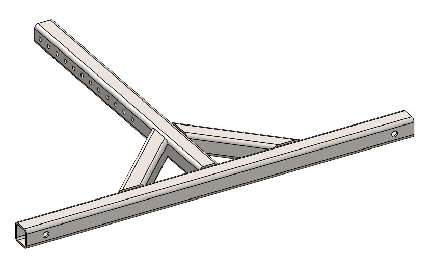
Step 2: Cut two pieces of 2 x 2 x 12’’ long square tube.
Shape the ends at 45º using an angle grinder. Position them as shown on
the next figure and complete the welds according to the welding plan
(Fig. 1.1). Paint the frame in desired color.
Step 3: Cut
two pieces 5 x 8’’ of ¼’’ thick mild steel sheet. Drill the holes and
mill the slot according to dimensions in the main drawing. Mount the
steering head plate using the 3/8 x 3.5’’ bolts, nuts and washers as
shown.
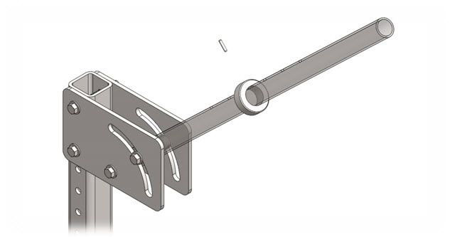
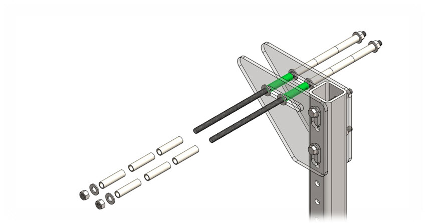
Step 4: Mount the steering head shaft using the
3/8 x 3.5’’ bolts, nuts and washers. During the assembling use 6 x 3/8’’
set of washers as spacers (colored in green).
Step 5: Mount the locking sleeve to the steering head shaft threading the 0.075’’ X 1.75’’ retaining splint.
Step 6: Thread
the 5/8 x 4.5’’ bolt, 5/8 washer and tight the 5/8 washer-nut. Screw
the 5/8 nut, but don’t tighten. Mount the square tube end caps.
2. Assembling The Right Stand.
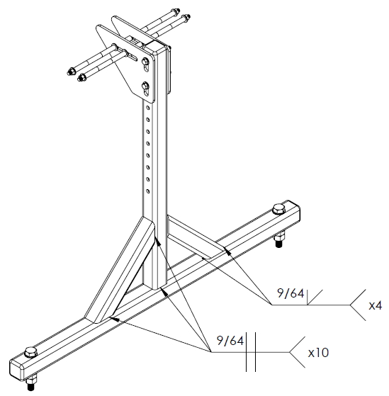 Fig. 2.1 Right stand assembly welding plan.
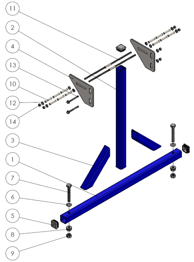 Fig. 2.2 Right stand assembly montage plan.
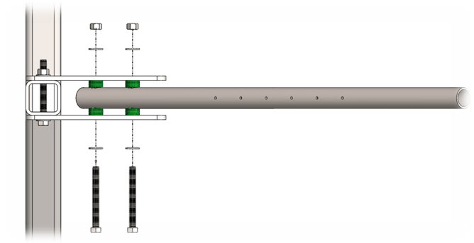
Parts:
1. Square tube 2 x 2 x 40’’;
2. Square tube 2 x 2 x 29.5’’;
3. Square tube 2 x 2 x 12’’ with 45º miter cut both ends;
4. Rear axle mount plate 6 x 8 x ¼’’
5. Square tube end cap;
6. 5/8’’ Washer;
7. 5/8’’ x 4.5’’ Bolt;
8. 5/8’’ Washer-nut;
9. 5/8’’ Nut;
10. Small tube 1.2 OD x 2’’;
11. Threaded rod 3/8 x 16’’;
12. 3/8’’ Washer;
13. 3/8’’ x 3.5’’ Hex bolt;
14. 3/8’’ Nut;
Repeat Step 1 and Step 2 from chapter one.
Step 1: Cut
two pieces 6 x 8’’ of ¼’’ thick mild steel sheet. Mill the slots
according to dimensions in the main drawing. Mount the rear axle mount
plate using the 3/8 x 3.5’’ bolts, nuts and washers.
Step 2: Take
two small tubes, position them between the plates and align them to the
slots (colored in green). Put in the threaded rods through the slots
and tubes. Thread the washers and the others small tubes. Tight with 3/8
nuts.
Step 3: Thread the 5/8 x 4.5’’ bolt, 5/8 washer
and tight the 5/8 washer-nut. Screw the 5/8 nut, but don’t tighten.
Mount the square tube end caps.

3. Frame Jig Height Adjustment Assembly.
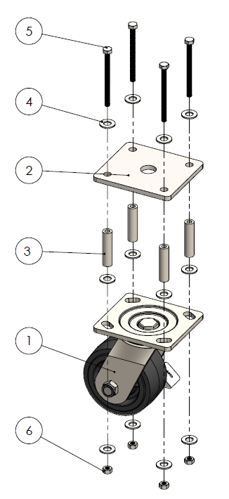 Fig. 3.1 Height adjustment assembly montage plan.
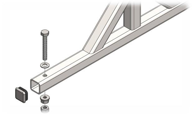
Parts:
1. Caster wheel CPS 40156TZ-ROI81(KK)TB.
2. Height adjust plate.
3. Small tube 1.2 OD x 2’’.
4. 3/8’’ Washer.
5. 3/8’’ x 3.5’’ Hex bolt.
6. 3/8’’ Nut.
Step 1: Cut four pieces 4.5 x 4.5’’ of ¼’’ thick mild steel sheet. Drill the holes according to dimensions in the main drawing.
Step 2: Take four small tubes, eight 3/8’’ washers and four 3/8 x 3.5’’ bolts. Arrange them upside down as shown.
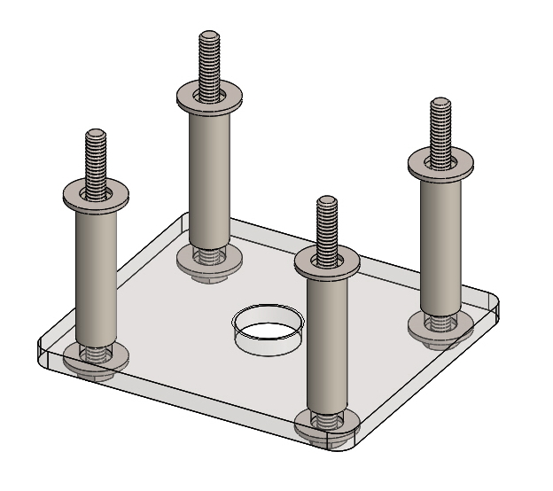
Step 3: Position the Caster wheel observing the montage plan (Fig. 3.1). Thread the 3/8’’ washers and tight the nuts.
Repeat the steps three more times, you will need four height adjustment assemblies.
4. How To Assemble The Motorcycle Frame Jig.

Before
start assembling the frame jig you have to produce part number 3 –
Angle iron 2 x 3 x 78’’ long, and part number 9 – Square tube 2 x 2 x
24’’ long. See directions in chapter 1, Step 1.
Parts:
1. Left stand.
2. Right stand.
3. Angle iron 2 x 3 x 78’’ long.
4. 3/8’’ x 3.5’’ Hex bolt.
5. 3/8’’ Washer.
6. 3/8’’ Nut.
7. Height adjustment assembly.
8. 5/8’’ Nut.
9. Square tube 2 x 2 x 24’’ long.
10. 3/8’’ x 3.5’’ Hex bolt.
11. 3/8’’ Washer.
12. 3/8’’ Nut.
13. Square tube end cap.
Step 1: Align
the holes of the left stand (1) and the front angle iron (3). Thread
the bolts (4) together with the washers (5) and then put in the rear
angle iron (3). Screw the nuts (6) together with washers (5), but don’t
tighten them.
Step 2: Position the right stand (2) according to
the montage plan (Fig. 4.1), between the angle irons. Align the holes
and repeat Step 1 directions. (NOTE: make sure that the used holes are
on the same level as the left stand, so the angle iron will be parallel
to the ground). Align the left and right stand to be parallel and
tighten the nuts. Check alignment again, if there is some discrepancy
repeat the last step.
Step 3: Turn to one side the obtained frame,
so you will be comfortable to mount the height adjustment parts. Screw
the height adjust plate (7) with the bolts as shown on Fig. 4.1. Mount
the rest three parts and turn the frame to normal position. Align the
height turning the wheel assembly and proceed to tighten the nuts (8).
Step 4: Mount the square tube beams (9) to the frame using the bolts (10), nuts (11) and washers (12). Use 3/8’’ washers as spacers between the beams and angle iron (3), see montage plan. Proceed to the last step, mounting the square tube end caps (13).
Congratulations!
You finished the Motorcycle Frame Jig!
Plans:
