How To Build A Chopper Frame!

Learning how to build a chopper frame build is a great project. It's rewarding in many ways.
In this article we're going to build a frame, in our heads mostly. And we are going with a chopper frame because that's what I prefer.
That's to say, you'll get the information you need, but you're still going to need commitment and some skill to make a frame from our words. But even if you don't build a frame, you'll know how it's done.
Of course it's pretty interesting to know how chopper frames are built, and in theory it's pretty easy.
Knowledge is power, as Francis Bacon said, and this site will put you in a position to ask the right questions and to talk intelligently about a how a frame is built and how the work that goes into preparation, fabrication, and assembly. And best of all you could build one yourself!
Many experts recommend buying an old chopper or cruiser, even one that doesn't work, as a first project, because then you'll have most of the bits, and you know that they'll fit. If you choose to do this, this guide will give you more than enough confidence to get going.
When it comes to a chopper frame build, most people start with two questions - is it cheap and is it easy?
Is It Cheap To Build A Chopper Frame?
Well, yes and no. As far as the frame is concerned, the raw materials cost about $100. After all, it's just some bits of steel. But you'll need some equipment to build the thing, and that's going to cost more.
If you really do know how to build stuff you can some save money on this as well.
If you know
someone with all the gear who'll let you use it, and you count your own
time as free, then building a frame can cost a hundred bucks or so (if
you make no mistakes, which is unlikely if it's your first time).
Is It Easy?

Again,
this depends on what you mean by easy. If you have a lot of experience
working with metal, are a pretty decent welder and love measuring
things, then I suppose it could be thought of as easy. Like so many
things in life, the theory is easy, the practice is much harder.
What will be covered?
- Naming The Frame: Rigid and Swing Arm (Softail)
- Frame Geometry
- Rake And Trail
- The Tools For The Job
- Preparation
- Frame Building
What This Chopper Frame Guide Is and Is Not!
This guide IS a detailed explanation of everything you need to know about how to build a chopper frame.
This guide is NOT:
- A teaching guide for someone who can't weld or has never tried to build anything ever, particularly a motorcycle frame build.
- A set of plans. There are hundreds of different motorcycles out there, and hundreds of different ones yet to be built - I can't cover them all. So, though I'll talk about the different setups and the customizations, you'll need to design or buy your own plans for the exact frame you want. You can buy original precise plans here.
- A way to build a chopper for nothing.
A little advice:
From the start of your chopper frame build be realistic about what you can do - don't set out expecting to build the world's finest looking, best performing chopper at your first attempt.
Do you really believe all
those other guys who've been building choppers for years are stupid and
talentless? Of course not. (Or maybe you do believe that?) The truth is
that constructing anything that works is something a first-timer should
be really, really, proud of. Most don't get that far - how many people
do you know who've built a chopper up from a pile of metal on the floor?
Remember,
learning how to build a chopper frame is serious stuff. You're going
to build a bike that someday you'll be riding. Ask yourself questions
like, "can I weld?", or more precisely, "can I weld sufficiently well to
be confident riding along at 100 miles per hour relying on my welding to
protect me?" Of course, if you can't weld, you can learn by taking
classes and getting some good instruction, or you can get someone else
who you trust to do it.
 |
 |
Build a softail rigid bobber starting with these bobber frame plans.
Naming The Frame!
Most people reading this will know this part pretty well, but it's worth recapping.
Here's a two dimensional diagram of a rigid frame, the simplest type to build:
Parts Of The Frame - Orientation:

The parts made of tubing that make up the special shape of each bike are:
- The Wishbone Tubes that run along the top and the back of the bike. These two tubes are bent to make space for the seat. They get welded together and then to the top tube at one end and the bottom rails. (This is on a rigid frame - on a swing arm you weld them to the 'side plates'.) When the two pieces that make up the wishbone tubes are welded together they are shaped like a wishbone.
- The Top Tube or Backbone runs from the wishbone tubes to the neck stem, and is welded to both.
- The pair of Bottom Rails have the most serious bending and are welded to the neck stem at the front and the wishbone tubes at the rear (or side plates if you are building a swingarm frame). The Downtubes are just one part of the bottom rails; the section that comes between the neck stem and the first big bend.
- The Center Post or Seat Post is just a tube welded to the backbone and a crossbrace that runs between the two bottom rails (see the overhead few further on). It's there to make the frame more rigid, and it's worth noting that not all designs include one. If this is the case they clearly need to gain extra rigidity from else where.
This is our frame from above - the wishbone shape is very obvious now, and it's easy to see how the steering is attached:
Wishbone Shape Of The Frame:

There are usually three parts around the neck. The Neck Stem is the tube where the frame connects to the forks. It's machined steel, and will be fitted with bearings of some kind so it can support the front end of the bike. Because it has this vital role, there are two further parts that help out by adding strength.
The Neck Gusset Tube is a tube welded to both the backbone and the bottom rails. The Neck Gusset is a flat piece of steel that connects all of this together, again adding strength. The neck gusset is usually welded to everything in sight - the backbone, neck stem, neck gusset tube and the bottom rails.
There are many variations on this theme; many frames have no gusset but do have struts between the downtube and the neck stem, for example.
Here is a little diagram to show the gusset welds:
Detail Of The Neck Gusset and Neck Gusset Tube:

That's it for the basics of the frame. Now we need to think about how we're going to secure the engine, transmission, rear wheel and gas tank to the frame. When we plan and build the frame, we need to put thought into these few other essentials, known collectively as the mountings.
Chopper Frame Mountings:

Mounting essentials for securing the engine, transmission, rear wheel and gas tank to the frame:
- Top Mount Bracket
- Motor Mounting Plates
- The Forward Control Adapters
- Transmission Plate
- Seat Clip
The engine is fastened in place by the Top Motor Mount Bracket or Engine Mount, a heavy steel bracket which is welded to the backbone (in the diagram above it is roughly halfway between the tank clips and the seat clips, hanging down with a bolt hole drilled in it), and the by two Motor Mounting Plates or Engine Mounts on which the motor will sit. All three are labeled engine mounts in the illustration.
The motor is bolted to these mounting plates (there is a standard engine bolting pattern) so the engine is secured at three separate points, one or two of which are large machined, pre-drilled, steel plates. It's cheap and easy to buy the motor mounting plates to suit the engine you choose.
The Forward Control Adaptors are threaded lugs to which the forward controls will be fitted. They sit by the forward motor mounting.
The gas tank is held by the well named Gas Tank Mounting and Tank Clips- on the illustration below I've only shown the tank clips, because most often the mounting is fabricated using the gas tank as a guide later on in the assembly.
It's usually a small flat plate that matches the bolt
holes in the tank which is welded to a mitered tube that you measure
in-situ, and this is then welded to the frame. This way the gas tank
fits snugly and can be removed by using the bolts. The tank clips that
are shown sit between the two halves of the assembled tank, in the ridge
that runs through the center at the bottom of the tank.
Towards
the back of the bottom rails, behind the center post, we mount the
Transmission Plate, and bolt the transmission to it. The plate itself
can be welded to the frame, or bolted, and again can easily be bought
ready machined for your choice of transmission.
Finally there
needs to be a Seat Clip which will be fixed to the top of the wishbone
tubes somewhere in front of the center post, and onto which the seat
clips. Obviously you need to know what seat you're going to be using
before fitting this, and it can be left until late on (but usually
before painting).
A Word About Swingarms.
Hardtail: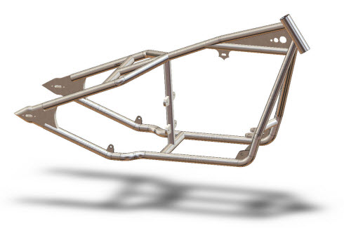 |
Softail: |
The frame on the left is our Sportster style hardtail frame 250 millimeter. The frame on the right is our specially designed softail (swingarm) bobber style frame 200 millimeter.
Here we're concentrating on rigid chopper frames, but it is possible to build a swingarm frame.
The swingarm is the rear portion of the frame and is used to hold the rear wheel in place and allow for movement as part of the rear suspension system. It's attached to the frame on a pivot axle and needs a suspension system bolted between the frame and swingarm to limit the movement of the swingarm. Swingarms can be bought made up, in which case you can fabricate a frame to fit it.
Such a frame will look similar to those above but will not extend to the rear axle, but rather will have a half diamond shape rear portion to accommodate the diamond shaped swing arm section.
Frame Geometry:
Here we discuss frame geometry; an important area to be familiar with as you learn how to build a chopper frame.
In
all Cruisers, the foot pegs and shifter are located a long way forward
so your legs can stretch out. On a well designed bike, this is a
comfortable riding position - Cruisers make good touring bikes because
of this feature combined with their stability at high speeds.
A badly
designed Cruiser drops all your weight onto your Coccyx (tailbone) and
is a far from comfortable ride. The placement and shape of the
handlebars stretch the arms out and add to the laid back style. Choppers
are an extreme, stripped down variation of the Cruiser, with larger
front fork rake and banana seats. Choppers carry a V-twin engine,
usually a big one.
The frame geometry is how this look and style is achieved. Here's the frame diagram again:
A Chopper Frame Without Mountings:

Different choppers looks are achieved by changing the length of parts of a standard frame. It's what's known as stretching. Extend the downtube for example and you can get a more obtuse angle for the forks and a longer overall bike (the front wheel moves further away from the frame). It's done for looks, for a better fit for a particular rider, or to change the way the bike handles.
It isn't done by just welding an extra few inches into the frame where you want to stretch it, but is done at the time of building the frame, with all the angles and lengths carefully worked out.
To understand this frame geometry section easily, I suggest getting some paper and a pen and doing some drawing of your own. By the end of this section, you'll be able to design the chopper of a stickman's dreams!
Stretching takes place in these three main areas -
- In the rear by extending the wishbones and bottom rails
- Up by the neck by extending the top tube and in the downtubes to shift the angle of the neck.
This frame geometry diagram shows where I mean:
Where The Stretch Takes Place:

Stretching The Rear:
This is what happens when you make a rear stretch. The axle has effectively moved up, lowering the bike:

Next in our chopper frame geometry section is a stretch in the front end. In this case a combination of two of the stretches I mentioned above. In this case the effect has been to lengthen the bike without altering the rake.
If just the bottom tube had been extended then the rake would have grown (see below for the full explanation of rake!):
Stretching Forward By Extending The Backbone:

Frame Geometry Conclusion:
With your pen and paper you can draw entire bikes to see what happens to the frame and the rest of angle of the ride and forks, the height of the ride from the ground and so on. To understand the change in handling characteristics that result from stretching the frame, we need to look at rake and trail.
Understanding Rake and Trail!
30 Degree Rake:
Rake is simply the angle formed by a line through the neck stem with a vertical line drawn to the ground when the bike is standing. It looks like this:

40 Degree Rake:
As you know, choppers have a larger rake angle that most other motorbikes:

Zero Rake?
A zero rake is when the neck points straight at the ground, and you never see it in a bike. You would have something impossible to handle - a clown's unicycle and a shopping cart both have zero rake.
Generally, speaking machines with larger rakes will be great for stability and going in a straight line, but less good for tight maneuvers than those bikes with smaller rakes.
This is simply because increasing the rake moves the front wheel further away from the rest of the bike, increasing the overall length and therefore the turning circle. So a large rake usually means the bike is good for cruising on the highway. A sport bike may have a rake of 24 degrees, a cruiser 32 degrees, with ten to fifteen inches difference in their wheelbase dimensions. Each is designed for a different purpose.
Trail is a relationship between the front wheel axis and the steering axis, measured as shown in the diagram below. It's measured in inches, and you can easily measure it yourself with a tape measure and a stick.
A Diagram Illustrating Trail:

Most bikes have a trail between 2 and 4.5 inches. It can be altered by changing the neck rake, the fork length and type, triple trees, and the wheel diameter.
This is not a hard a fast cut-off point and good bikes can be built with trails either side of the normal range, including a zero trail. If we go much larger than five inches or so we would get a bike that's really stable at speed, probably handling sluggishly, and which at low speed is going to be difficult to keep in line.
It is possible to end up with negative trail (where the wheel axis is behind the steering axis) if you use some kind of extension at the bottom of the neck to force out the forks without doing any frame alterations - triple trees that do this are available.
Everyone agrees that this is dangerous however, since the machine may handle in unpredictable ways at speed and on corners, which is never a good idea. Out of interest, it looks like this:
A Diagram Showing Negative Trail (Bad)!

How To Build A Chopper Frame:
The Raw Materials You'll Need!

The main frame component is tubing. Tubing is measured by it’s size on the outside, so 1.25 inch tubing has an outer diameter of 1.25. Piping on the other hand, used for plumbing, is measured by the inside size so 1.25 inch piece of pipe would be fatter than similarly labeled tubing. Frames can be made of piping, but it’s very bad.
They are going to end up very heavy and quite simply the material is wrong for the job. Don’t confuse massive weight with strength - you should be able to carry the frame reasonably easily when you’ve finished it because t should weigh about 40 pounds.
Cold rolled electric resistance welded steel (CREW) is the standard choice, but there are other materials you could use. Chromoly is an option for the tubing, but it is more expensive - probably unnecessarily so. For certain components like lugs (the forward control adapters for example), the slightly more expensive seamless steel know as drawn over mandrel or DOM will be needed. DOM can be used throughout the chassis, but again it pushes the price up unnecessarily.
Needless to say each builder will have his or her own ideas on the right material for the job.
There are various tubing diameters that you can use safely, though most bikes are built from between 1.2 to 1.5 inch diameter CREW with a wall thickness of between 0.095 and 0.120 inch. To get a good mixture of weight and strength, the wall strength can be increased in the center post and backbone whilst keeping the same outer diameter tubing yet with a thinner wall for the rest of the frame.
You could use 1.25 inch diameter with a thickness of 0.095 inch for everything but the center post and backbone, then a 0.120 inch wall-thickness for these parts. The larger tubes of 1.5 inch diameter will make for a heavy chassis if you use the same wall thickness, but the larger tubing is easier to cut and weld for less experienced fabricators.
When you decide on the diameter and type of tubing, you’ll need to buy two twenty foot stretches. Needless to say not all suppliers offer the same quality merchandise, and you’re looking for material that has been looked after. You should expect it to be clean and rust-free, straight and dent free.
Frame Building Tools:
There are many frame building tools and equipment that can be used in motorcycle frame manufacture - if you get chance to go to a medium sized workshop you'll see all sorts of exciting equipment (if equipment excites you). Here we'll stick to the basics.
A Saw:

You'll need a good saw for cutting tubing, so a hacksaw works. However better cuts come from a tubing cutter, a jig saw, or a reciprocal saw.
The Porter Cable saw above is the one I own today. It's a good one and it's super cheap.
Measuring and Setting Equipment:
A
plumb bob is a necessary frame building tool because you will need to
find vertical along with a good quality steel tape to measure tubing
lengths and so on.
For the more accurate work you need a
machinists square with a level and calibrations in small factions of an
inch (imperial 32nds and 64ths and 'metric' hundredths of an inch) and
some accurate calipers. You will also need an angle finder for
accurately setting the angles in assembly. Something like a felt tip pen
will do for marking off measurements on the tubing.
Something to Cope or Notch the Tubing:

This is a motorcycle frame building tool that makes the notch in the end of the tubing prior to welding to another tube (welding the downtube to the headtube, for example).
It needs to make a cut that is the shape of the
tube it's going to be welded onto, and to make that cut at the correct
angle so the two parts fit snugly before welding.
The job can be
done with an angle grinder set on a bench and some modifications, but
this needs a lot of skill. There are specific tools for the job, called
notchers, which vary in quality and price. The cheaper ones may not do
the job very well because they may be inaccurate, and often only miter
to 45 degrees, when you'll be needing more. You should be able to buy
one for around 100 to 150 dollars that will do the job.
Tubing Bender:

It's possible to bend pipe by hand if the
pipe is long (so you can get leverage) and you don't care too much about
the exact shape. All you need is to something to wedge the pipe.
However, you're looking for something with much more accuracy that will
work on already cut (i.e. short) tubing. It needs to be something
specifically designed to bend bike tubing, not something that bends
pipes.
The benders specifically designed for bending plumbing
pipes that are based around a bottle jack aren't much good because they
won't allow tight enough bends - you'll need to bend around part of a
circle that measures 3 to 5 inches (imagine the bending mold, which is
only a section of a circle, made into a full circle - the radius of this
imagined circle is the bend radius).
A good tubing bender will
be around $500, and with $1000 should get you a good hydraulic one.
Check on the specs that it does what you need it to do, that it has
capacity for all the size tubing you'll be using.
For different
size tubing you'll need different size molds or dies so the tubing
nestles comfortably whilst being bent. (Often the dies are called
mandrels, though strictly speaking that's something you put inside the
tube to improve the post-bending shape, and which we won't need.)
Another option is to build your own tubing bender.
Frame Jig:
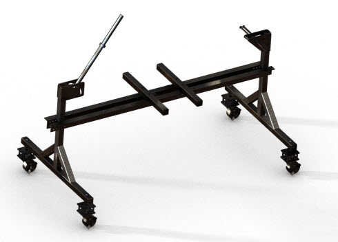
A frame jig is one of the most helpful frame building tools you'll have in your shop. So it requires it own page. Click here to read more about the frame jig.
A frame jig for your chopper frame is
what holds the tubing lightly in place, at the correct angles, while you
are welding it.
A chopper frame can be built without a frame jig
and some top custom builders do just that. But they are top custom
builders, not beginners. Most builders consider a jig vital - and it
probably is an essential for a beginner. They can be quite basic - if
you were building a bicycle (which is flatter and lighter than a chopper
frame) a marked out piece of plywood with a few bits of shelving
bracket would be more than enough to do a great job.
If you want
you can spend thousands of dollars on a shiny adjustable frame jig that
will do the job. It's also possible to build your own, which we'll talk
about below. The problem is that this takes time and money - more of
both than the building of the frame itself. So if money is no object,
you might want to buy a jig. You can get professional, original jig
plans here.
Or, you can make your own jig (great project, by the way).
There are many types of frame jigs available - what
is usually just referred to as a 'frame jig' is designed for holding all
the metalwork of the frame in place for given bike. In other words it's
useful for the frame only.
A 'custom builder's' frame jig
usually takes all the components (wheel, motor and transmission) as
well, so the frame can be built around these bits. This helps in
ensuring that they all fit well because you have all the parts in front
of you as you fabricate the machine. And finally there are the parts
jigs, which are simply used for bits and pieces like fabricating the
wishbone and downtube before bringing them together with the rest of the
frame.
There are many different names for a jig - basic flat
plate, modified flat plate, parallel beams jig, compact plate jig,
bottom up jig, external jig, to name but a few. Here we'll just talk
about the basics that you will need to complete the job. The building of
a jig is a chance to stretch your ingenuity; not all jigs need to be
the same!

The first thing that all jigs need is a solid base that is true (perfectly level). This doesn't in itself have to be hi-tech, and can be metal girders stacked on blocks or set on a perfectly level workbench.
Some jigs are vertical and you build the bike as though it
was balanced on its back wheel, but I find it easier to visualize the
bike in the position it is going to end up being ridden.
Next you
will need some fixed points of reference for putting the bike together,
such as fixed tubes for sliding the neck tube onto (fixed at the
correct angle) and for mounting the axle points.
Also you need to remember that once the frame is welded, it needs to come off the frame jig to become a street going vehicle - don't jam it in place with an immovable axle mount and an angled neck support strut!
Frame Preparation for Assembly!

Chopper frame assembly requires preparation, patience, and the right tools and some skill at welding:
Shops
that make large numbers of frames will have a set of pre-bent tubes and
other essentials set aside in bins. They physically and mentally
separate prep work from assembly, and it's not a bad idea for the first
time builder since you need different attitudes for the big cuts and
bends and for the fine work.
When attempting a motorcycle frame
assembly for the first time, it's important not to rush. Use a lot of
mockups before committing yourself, and measure (at least) twice. Don't
rely solely upon the measuring instrumentation; use the metal in front
of you wherever possible,
Get your
plans, your tools, and your raw materials in a sensible order. We'll
start out bending and cutting the metal. The basic list will be
something like this:
- 1x backbone
- 2x bottom rails (long pieces with several bends)
- 1x center post
- 2x wishbones
- Some cross struts etc.
Neck
Stems can be made from DOM (which unlike CREW has a seam free
interior), but an also be bought as complete kits with bearings. This is
a fairly inexpensive and recommendable option.
Similarly the
mounting plates for the transmission and the motor can be machined if
you have the skill and time, but can cheaply be bought for you to put in
place.
With the plans at hand, mark
up the tubing for cutting and bending. Leave some extra inches (about 2
inches at each end) when making the first cuts, since the tubing needs
to be fine fitted in situ. Bending, even with the right equipment, isn't
easy to get right first time.
Possibly, you'll not be able to see the scale telling you what angle you're at whilst you're in the process of making the bend, so you have to keep stopping to check during the frame build.
More importantly, metal doesn't behave like modeling
clay - it has elastic properties and 'springback' will take place. This
means you have to bend a bit more than you need, because the metal will
return to a slightly larger angle when it's out of the bender.
This
might not happen immediately, which is why even in professional shops
they often have to do a little further precise bending in the motorcycle
frame assembly stage.
Unbending is close to impossible however, so
you're best to take a gradual approach to the bending, particularly
until you have a good feel for the metal's bending properties - this
feel comes with experience.
The
other thing to note when working with metal is that warm metal changes
size (it expands as it heats). This is crucial to remember when doing
the fine grinding to get the final fit. The grinder heats the metal up
and makes you over measure by small, but important, fractions of an
inch.
Wait for the metal to cool between fittings. Obviously the
effect is greater on the smaller pieces like struts, but the physics is
the same on all the metal parts you work. The finished miter needs blunt
edges rather than sharp ones in order to successfully weld later on.
You're
looking for flat contact between the cut edges and the tube it will
attach to so the whole thickness of the cut tube is in contact, not just
a thin, knife-like profile. For this reason don't use a 1.25 hole saw
fitting on a 1.25 tube, but choose a slightly smaller diameter.
Welding The Frame!

Ron Covell TIG welding a rigid frame in the jig.
Welding
is a skill that comes from being taught (it's a difficult skill to
learn from a book), from practice, and from continual use. Many welders
will tell you that their standard falls away sharply if they aren't
practicing regularly. So if you can't weld at all, it's probably not a
good idea to learn on a motorbike frame.
If you can weld, there are a number of things that can be done to maximize the chances of producing acceptable quality work.
Frame
and welding preparation is vital. The pieces to be welded should fit
smoothly together before being welded. Bear in mind that there is
shrinkage during welding (you're melting and remaking the metal), so
allow a small amount extra.
When welding, employ a pattern just
like you would when fitting an automobile wheel, tightening alternate
nuts. Tack weld the whole frame in place, then when you're happy, start
with a quarter weld on any particular joint, then switch to the matching
joint on the opposite side of the bike and do the corresponding
quarter.
The aim is to balance the welding as you go along to minimize
any frame twisting or movement. This can be done in or out of the jig,
depending on the type of jig and your personal preference.
Final Assembly!

Here's Ron fitting the centerpost during final assembly of his Chopper Chassis build.
Now you have the large parts bent, all your components to hand, and a jig in front of you, it's time to being. This next part needs precision and pride. All builders have a different way of approaching this section - I'll just run through one way.
You may find
you'd prefer to start with different parts. In any case, the key is to
build it up before welding. Check the measurements - make sure the
tubing fits together, make sure the motor and transmission will fit and
so on. Now here's a frame building sequence.
Clamp the
steering head into the jig. The measured and bent downtubes can then be
placed in the jig - make sure they are now at the same angle to give a
perfectly square finished frame. It's not uncommon (even for experts) to
have to bend one a little more. You can't say the whole thing is close
enough and the welding will fix it up. You don't want any unnecessary
stresses in the frame.
Mark with a pencil where the notching needs to be once the frame is
mocked up like this. After notching check again before the final
grinding or hand finishing. You need a very good fit here - filling gaps
with welding material is not a substitute for a well made joint.
In some jigs we can now place the backbone, the transmission plate and engine mounts in place, then the centerpost and any cross pieces. In other jig arrangements some of these parts will be done separately. The point is to get to a mocked-up version of the frame, with everything where is should be.
Later problems will be caused if the measurements
are wrong around where the engine and transmission will fit. The
clearances aren't usually huge (depending on your plans and intended
choice of motor), so this should be checked with care before proceeding
to the welding stage. Although some mistakes can be cured later, it's
best to avoid getting to that stage.
Tack welding should be done at all weld points first of all to help
minimize any twisting that might happen during welding. At this point it
should be possible, though certainly not necessary, to remove the frame
from the jig. The jig is not a thing to clamp everything tightly in
place whilst you weld it together - if this were the case the frame
could twist and bend when you remove it. What makes the frame stay
straight is the fit of the components you have made. Keep the frame in
the jig and move the jig around until you need to remove it to weld the
last few unreachable welds.
Weld the remaining hangers and brackets using the components themselves as a reference if possible.
Stand back and admire your frame!
Suggested Reading: