Softail Bobber Frame Assembly Guide!
If you want to build a softail bobber frame using our plans but you are not sure how to do it, this step by step tutorial will be your guiding hand.
We created the guide so that an intermediate or possibly even a novice fabricator can fabricate a frame in their garage.
The plans for this frame build are required. In addition, we are using our jig in the step by step directions, which is located here, as the jig to build the frame.
Machinery and Tools You'll Need:
1. Frame jig (recommended).
2. Chop saw or Angle grinder.
3. Tubing bender.
4. Tube notcher and tube notching accessories.
5. MIG, TIG or Arc Welding.
6. Fitter’s vise.
7. Hammer, wrench set, tape measure, caliper.
8. Drill press.
9. Drill set.
Materials Required:
1. 1.25’’ ERW tubing (35 ft).
2. Mild steel sheet – 1’’ thickness (120 in2).
3. Mild steel sheet – 0.5’’ thickness (100 in2).
4. Mild steel sheet – 0.3’’ thickness (15 in2).
5. 2’’ round bar (8 in).
6. (1) Steering head 8’’.
7. (2) Steel cone insert.
8. (1) Spring suspension rod.
1. Preparing The Frame Jig.
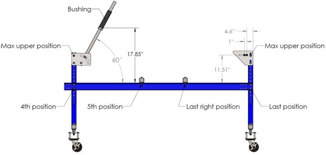
Step 1: Position
the basic elements of the frame jig in proper position as shown on the
figure. Move the elements in the specified position and tighten the
bolts.
Step 2: Using the vertical slots of the rear axle
mount plate perform the 11.51’’ dimension. Moving the threaded rod in
horizontal slot perform the 4.6’’ dimension and then position the second
rod 1’’ to the left. Tighten with nuts to ensure the position of the
rods.
Step 3: Position the steering head shaft 60º
measured from the longitudinal beam, so the steering head of the bobber
frame have to be with 30º rake. If you need 40º rake position the shaft
50º measured from the longitudinal beam.
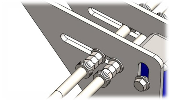
Step 4: Prepare
bushing depending on dimensions of the used steering head. Position
locking sleeve observing the drawing and lock it using the retaining
splint. Thread the bushing as shown on the picture.
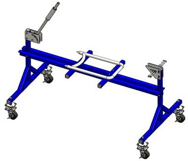
2. Assembling The Main Frame.
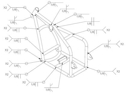 Fig. 2.1 Main frame assembly welding plan.
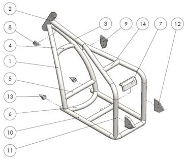 Fig. 2.2 Main frame assembly montage plan.
Main Frame Assembly Parts:
1. Down rails.
2. Steering head.
3. Backbone.
4. Small curved brace bar.
5. Straight cross bar.
6. Large curved brace bar.
7. Rear mount gusset.
8. Steering head gusset.
9. Engine top gusset.
10. Base bottom bar.
11. Rear vertical rail.
12. Hinge plate.
13. Steel cone insert.
14. Rib.
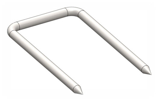
Step 1: Cut
64’’ long piece of 1.25’’ tubing. Execute the R2.0’’ bends observing
the dimensions on the drawing. Check dimensions. Weld the steel cone
inserts to the both ends.
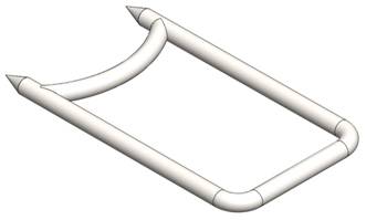
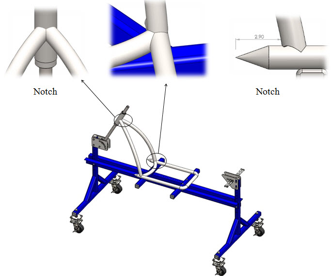
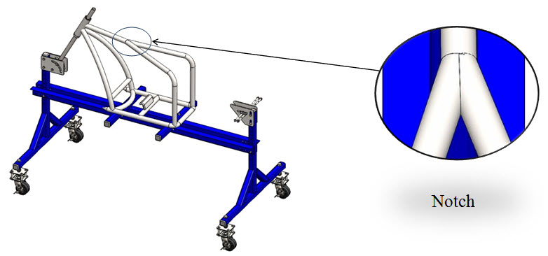
Step 2: Cut a piece
of 1.25’’ tubing. Bend the 10’’ radius observing the drawing and then
cut the proper length. Notch the ends so they have to fit to the radius
of the tubing. Tack weld to base bottom bar.
 |
 |
Step 3: Position the already made base bottom bar on the frame jig as shown on the next picture. Thread the steering head through the already mounted to the frame jig bushing.
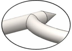
Step 4: Cut two 27’’ long pieces of 1.25’’ tubing and bend the 29.2’’ radius. Notch the ends using a tube notcher. Holding the first bended tube tack weld in place. Repeat the step for the second tube. Make sure to comply the dimensions for correct position.
Step 5: Cut two 12’’ long pieces of 1.25’’ tubing. Notch the ends and tack weld one of the bars to the base bottom bar observing the dimensions on drawing. Weld the second piece between the down rails. Use welding fixtures if available for right positioning.
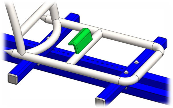
Step 6: Cut a 4 x 6’’ piece of 0.5’’ mild steel sheet. Bend according to dimensions on drawing. Tack weld to the straight cross bar. Use welding fixtures if available.
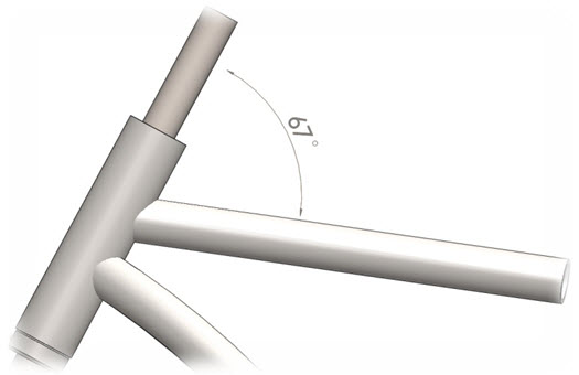
Step 7: Cut 18’’ long piece of 1.25’’ tubing. Notch the ends of the tube. Position about 67º relative to the steering head, but you have to watch for compliance the dimensions too. Tack weld in place and check the alignment again, if there is some gap in dimensions cut the piece and repeat the step.
Step 8: Cut
35’’ long piece of tube. Bend R4’’ radius according to the drawing.
Then proceed to cutting the final length. Notch the ends as shown on the
picture. Holding the first tube tack weld in place and then proceed to
the second piece. Check dimensions and if there is some gaps cut the
pieces and repeat the step.
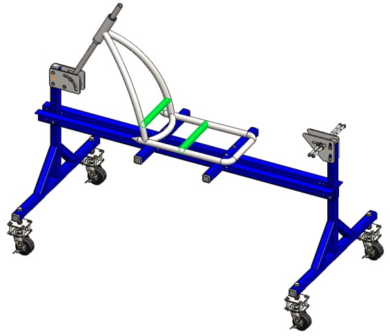
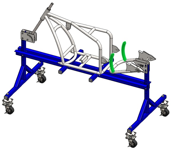
Step 9: Cut a piece of 1.25’’ tubing. Bend the R12’’ radius observing the drawing. Notch the ends until you get the proper length. Tack weld between the down rails (colored in green).
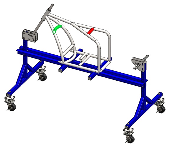
Note: Don’t proceed to
welding the piece colored in red. This will be the final piece added to
the frame to comply the dimensions between the main frame and the soft
tail.
Step 10: Proceed to checking all the dimensions of the
frame. When you are convinced everything is correctly aligned complete
the welds according to the welding plan (Fig. 2.1).
Step 11: Cut two pieces of 0.3’’ thick mild steel sheet. Shape according to the drawing and weld the pieces to the frame observing the montage plan (Fig. 2.2).
Step 12: Cut two pieces of 0.5’’ thick mild steel sheet. Shape according to the drawing. Position the first piece in the middle of the straight section and complete the welds observing the welding plan (Fig. 2.1). Repeat for the second piece.
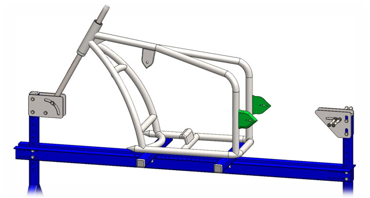
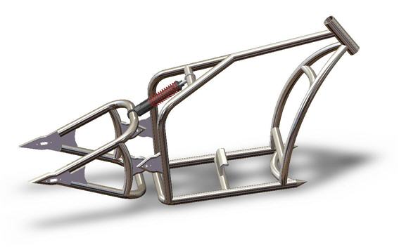
3. Assembling The Softail.
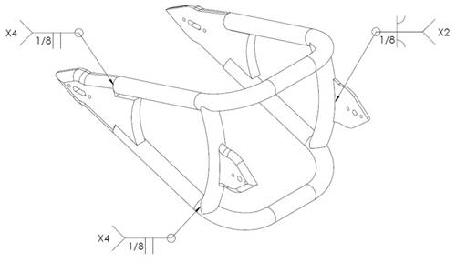 Fig. 3.1 Soft tail Welding plan.
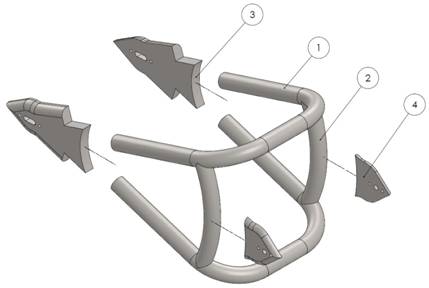 Fig. 3.2 Soft tail montage plan.
Parts:
1. Upper and lower wishbone.
2. Small curved brace bar.
3. Axle plates.
4. Hinge plate.
Step 1: Mount
the axle plates in their place on the frame jig. Use two threaded rods
to ensure the horizontal position of the slots. You can use the two
small holes to ensure the 11.5’’ size and fix the plates not movable.
Step 2: Cut two 43’’ long pieces of 1.25’’ tubing. Execute the R4.3’’ bends observing the dimensions on the drawing. Check dimensions and proceed to welding the lower wishbone. Holding with hand the tubing align with the outside radius of the hinge plate. Tack weld in place. You can use welding fixtures if available for easier positioning.
Step 3: Cut two pieces of 1.25’’ tubing. Bend the R13’’ radius observing the drawing and then cut the proper length. Notch the ends so they have to fit to the radius of the tubing. Position the first piece and tack weld (see the drawing). Check alignment and proceed to welding the second piece.
Step 4: Repeat
Step 2 for mounting the upper wishbone. Check all dimensions and if
there is no gaps complete the welds observing the welding plan (Fig.
3.1).
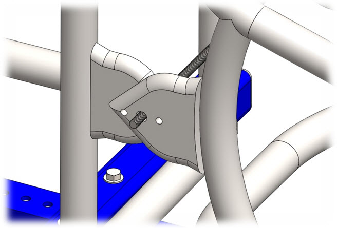
Step 5: Take the absorber and mount the one end to the
upper wishbone. Mount the rib (Fig. 2.2 number 14) to the other end.
Position the rib on the right place of the main frame. Mark with sign
the right position and the proper length. Remove the rib and cut the
proper length. Weld the piece to the main frame and mount the absorber.
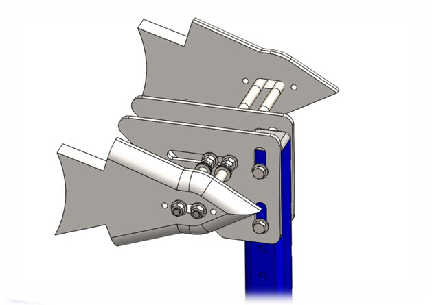
Step 6: Cut two pieces of 0.5’’ thick mild steel sheet. Shape according to the drawing, but don’t drill the holes. Align the pieces with the hinge plates of the main frame, mark the right place of the holes. Drill the holes. Position the first piece aligned with the holes (thread a pin or bolt through the holes) of the main frame hinge plates and complete the welds observing the welding plan (Fig. 3.1). Repeat for the second piece.
When all the steps are completed the welds must be finely filed to overflow with the tubes. Then proceed to custom painting the frame.
Congratulations!
You finished assembling the Softail Bobber Frame!
Plans: