How To Build A Tubing Bender!

If you want to build a tubing bender and you are an intermediate to advanced fabricator then get the plans here and follow the assembly guide below.
The steps below will help you stay on track, keep organized, and get it done with fewer problems.
Attention: If you are a beginner to intermediate fabricator you may want to follow this guide to building a bender. It's a simpler design, and it's easy to build.
Tools and Machinery Needed:
- Lathe.
- Milling-Drilling center.
- MIG, TIG or Arc Welding.
- Chop saw or Angle grinder.
- Fitter’s vise.
- Hammer, wrench set and caliper.
- Drill set.
Tubing Bender Build Materials:
The design of your frame must consider the horsepower and size of the engine which will be supported by the frame as well as the type of metal used to construction the frame. The three types of tubing used for bending a frame are, in order of strength, Chrome-Moly, Drawn over Mandrel (DOM), or Electric Resistance Welded (ERW).
Whatever type of tube you plan to bend you'll need to have access to a tubing bender. If you choose to purchase one, you will find that you'll need any investment of $300 for the least expensive as well as die sets which cost from $150 to $300 for each size of tubing you plan to bend for your frame.
- Mild steel square tube – 3⁄4’’ X 3⁄4’’ X G16’’ (12 ft).
- Mild steel square bar – 1 1⁄2’’ X 2’’ (3.5 in); 3’’ X 2’’ (2 in).
- Mild steel sheet – 1.5’’ thickness (40 in2); 1’’ thickness (27.5 in2); 0.5’’ thickness (489 in2); 0.25’’ thickness (40 in2); 0.1’’ thickness (1 in2); 0.04’’ thickness (6.5 in2).
- 10’’ round bar (2.5 in); 3-3⁄4’’ round bar (2.5 in); 2’’ round bar (2.5 in); 1 1⁄2’’ round bar (25 in); 1’’ round bar (4 in); 0.5’’ round bar (16 in).
- (4) Screw M8x1.25x30 ISO 4762.
- (10) Screw M8x1.25x12 ISO 4762.
- (1) Screw slotted M3x8 ISO 1207.
- (14) Spring Washer A8 DIN 128.
- (3) Washer ANSI FW 0.5.
- (1) Washer ANSI FW 1.
- (1) Washer DIN 6902 – A3.
- (1) Clevis pin 1 X 4.87’’.
- (1) Clevis pin 0.5 X 4.84’’.
- (1) Clevis pin 0.5 X 1.57’’.
- (4) Retaining splint DIN 94-3.2x20-C-St; 16. (1) Retaining ring 5160-47 S-0.473.
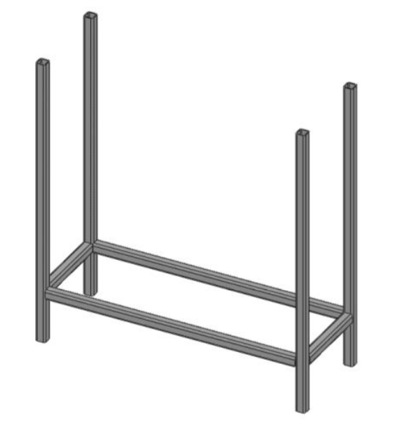
1. Frame Support Assembly:
Parts:
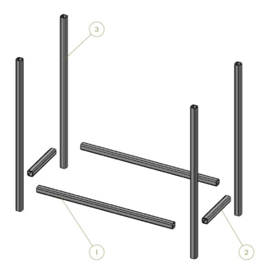
- Mild steel square tube 3⁄4’’ x 3⁄4’’ x G16 x 19.92’’ (BD125-00.00.301).
- Mild steel square tube 3⁄4’’ x 3⁄4’’ x G16 x 6.42’’ (BD125-00.00.302).
- Mild steel square tube 3⁄4’’ x 3⁄4’’ x G16 x 22.83’’ (BD125-00.00.303).
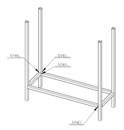
Step 1: Cut part numbers BD125-00.00.300-1 and BD125-00.00.300-3 according to drawing BD125-00.00.300. Lay the parts out on a flat work surface. Position them according to the dimension on the drawing. Tack weld them in place. Check alignment again and complete the welds according to the welding plan (Fig. 1.1).
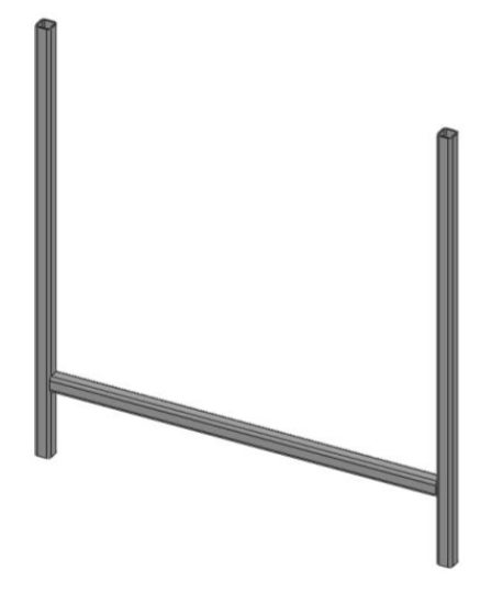
Step 2: Cut 2 pieces of part number BD125-00.00.300-2 according to drawing BD125- 00.00.300. Position them according to the dimension on the drawing. Tack weld them in place. Check alignment and complete the welds according to the welding plan (Fig. 1.1).
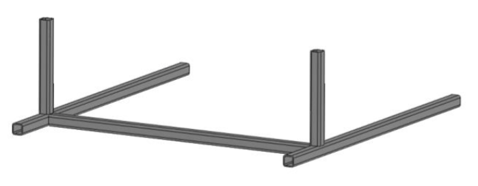
Step 3: Repeat Step 1 and position the two separate parts according to drawing BD125- 00.00.300. Tack weld them in place. Check alignment again and complete the welds according to the welding plan (Fig. 1.1).
2. 1.25" Tubing Bender Strickle Assembly.
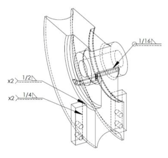 Fig. 2.1 Strickle 1-1/4 welding plan. Fig. 2.1 Strickle 1-1/4 welding plan. |
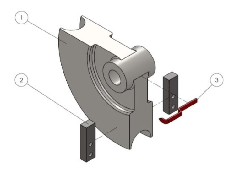 Fig. 2.2 Strickle 1-1/4 montage plan. Fig. 2.2 Strickle 1-1/4 montage plan. |
Parts:
- Strickle 1-1/4 (BD125-00.00.101).
- Shackle M8 (BD125-00.00.102).
- Degrees indicator (BD125-00.00.103).
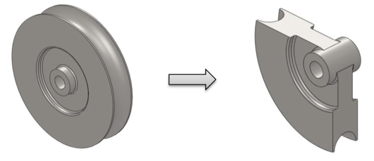
Step 1: Cut 2.5’’ work piece of 10’’ round bar. Turn it on a universal or CNC Lathe according to dimensions on drawing BD125-00.00.100. Cut one quarter of the part as shown on the next figure.
Step 2: Cut 2 work pieces of 0.5’’ mild steel sheet. Mill and drill the parts according to dimensions on drawing BD125-00.00.102. Complete the welds according to the welding plan (Fig. 2.1).
Step 3: Cut 4.1’’ of 0.1’’ mild steel sheet. Bend according to the dimensions on the next figure starting from right to left.
Step 4: Weld the obtained part BD125-00.00.103 to the strickle according to welding plan (Fig. 2.1). Paint indicator in desired color.
3. Assembling The Action Lever Strickle.
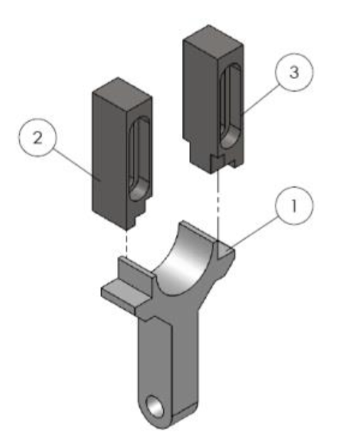
Parts:
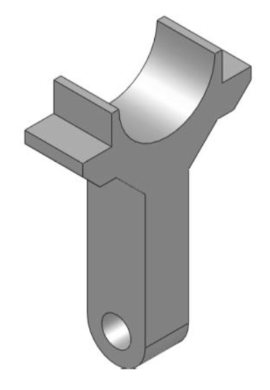
- Lever (BD125-00.00.201).
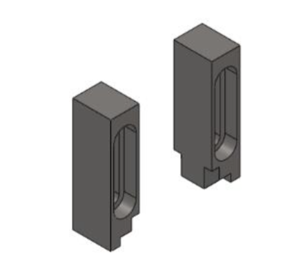
- Left shackle (BD125-00.00.202); 3. Right shackle (BD125-00.00.203).
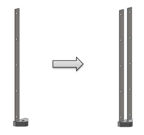
Step 1: Cut a 3x4.5’’ work piece of 1’’ thick mild steel sheet. Mill the shapes and drill the 0.504’’ hole according to drawing BD125-00.00.201.
Step 2: Cut two 1x3’’ work pieces of 1’’ thick mild steel sheet. Mill according to drawing BD125-00.00.202. Note that there is a left and right part.
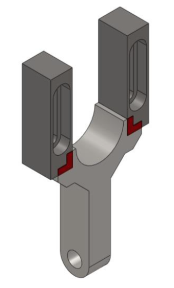
Step 3: Take the parts from Step 1 and Step 2, lay them on a flat surface and complete the welds according to welding plan (Fig. 3.1). Turn to the other side and repeat the welds. The result is shown on the next figure.
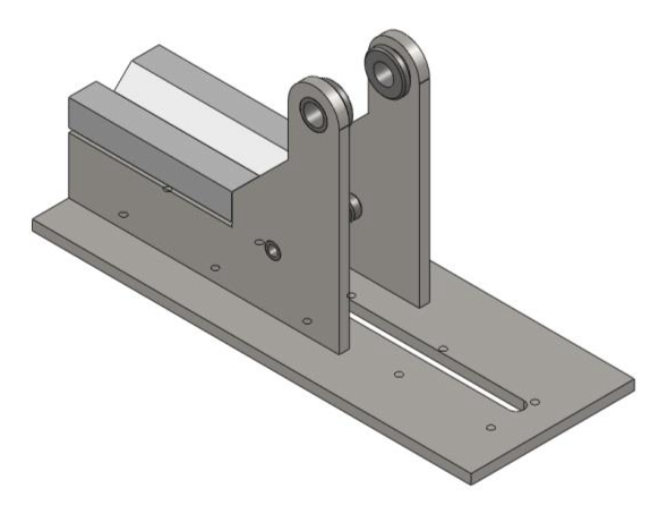
4. Tube Bending Device Assembly.
Parts:
- Table (BD125.01.00.001).
- Corbel (BD125.01.00.002).
- Wall (BD125.01.00.101).
- Little bushing (BD125.01.00.103).
- Big bushing (BD125.01.00.102).
- V guide (BD125.01.00.003).
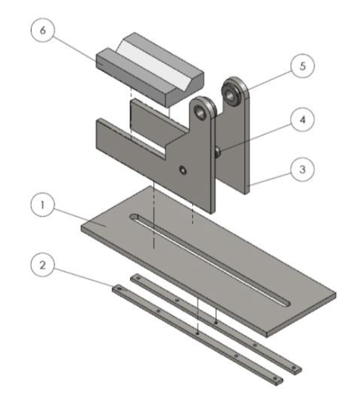
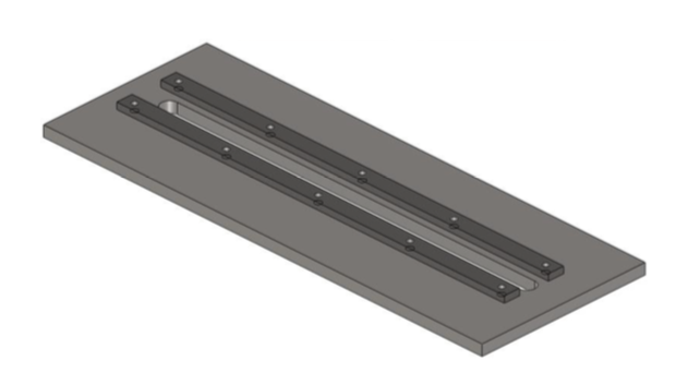
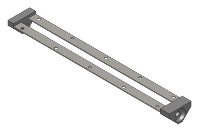
Step 1: Cut a 8x21.5’’ work piece of 0.5’’ thick mild steel sheet. Mill the outer contour and the groove in the center according to drawing BD125-01.00.001.
Step 2: Cut two 0.75x19’’ work pieces of 0.5’’ thick mild steel sheet. Mill to overall dimensions and drill the 5xM8 holes according to drawing BD125-01.00.002.
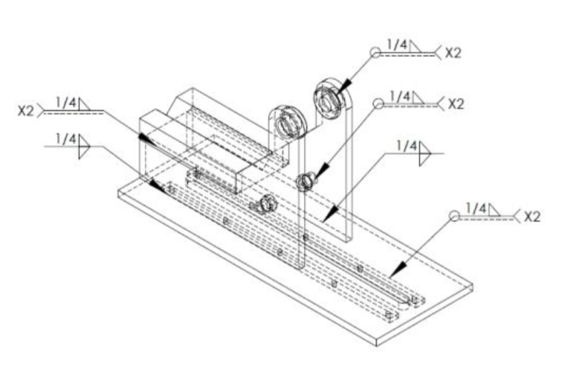
Step 3: Take the parts from Step 1 and Step 2, align them according to drawing BD125.01.00.000. Weld observing the welding plan on Fig.4.1.
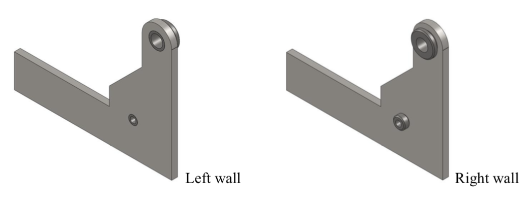
Step 4: Cut two 10x15’’ work pieces of 0.5’’ thick mild steel sheet. Mill to overall dimensions and drill the holes according to drawing BD125-01.00.101.
Step 5: Cut two 1.25’’ work pieces of 1’’ round bar and two 1.25’’ work pieces of 2’’ round bar. Turn it on a universal or CNC Lathe according to dimensions on drawings BD125-01.00.102 and BD125-01.00.103.
Step 6: Take the parts from Step 4 and Step 5, align them observing the drawing BD125.01.00.100 to get the Left wall and BD125.01.00.200 to get the Right wall. Weld according to the welding plan on Fig.4.1.
Step 7: Weld the obtained Left and Right wall to the part from Step 3 according to the welding plan (Fig.4.1) observing the dimensions on drawing BD125-01.00.000.
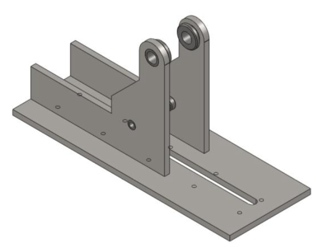
Step 8: Cut a 4.5x8.25’’ work piece of 1.5’’ thick mild steel sheet. Mill the overall dimensions and the 90 deg prism according to drawing BD125-01.00.003. Weld the V guide to the obtained part from Step 7 observing the welding plan (Fig.4.1) and drawing BD125-01.00.000. The final assembly is shown on the following figure.
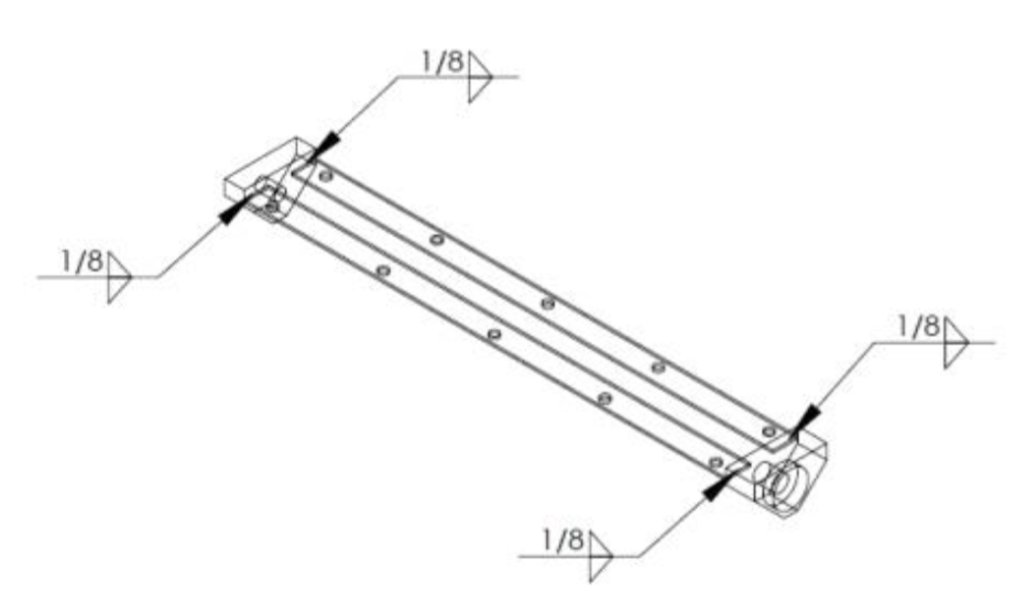
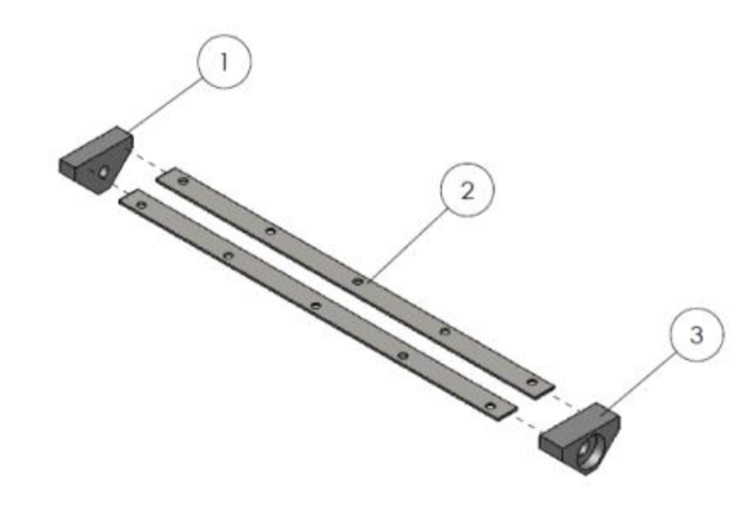
5. Screw Support Assembly.
Parts:
- Free cap part (BD125-02.00.102).
- Guide part (BD125-02.00.103).
- Bearing cap part (BD125-02.00.101).
Step 1: Cut a 2x3’’ work piece of 1’’ thick mild steel sheet. Mill to overall dimensions and drill the hole (NOTE the tolerances of the hole) according to drawing BD125- 02.00.102.
Step 2: Cut two 1x20’’ work pieces of 0.25’’ thick mild steel sheet. Mill to overall dimensions and drill the holes according to drawing BD125-02.00.103.
Step 3: Take the parts from Step 1 and Step 2, align them observing the drawing BD125.02.00.100 and complete the welds according to the welding plan on Fig.5.1.
Step 4: Cut a 2x3’’ work piece of 1.5’’ thick mild steel sheet. Mill to overall dimensions and drill the holes according to drawing BD125-02.00.101. Complete the welds according to the welding plan (Fig. 5.1) and dimensions on drawing BD125- 02.00.100. The obtained part is shown on the following figure.
6. Screw Assembly.
Parts:
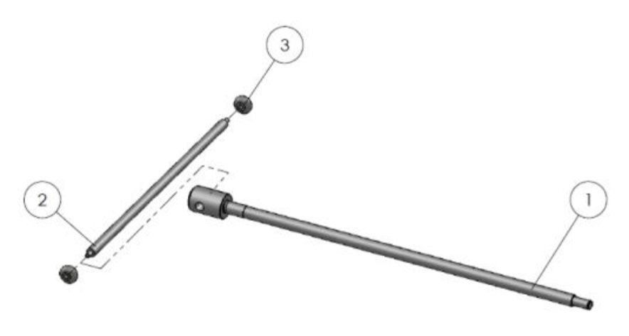
- Screw (BD125-02.01.001).
- Rod (BD125-02.01.201).
- Head rod (BD125-02.01.202).
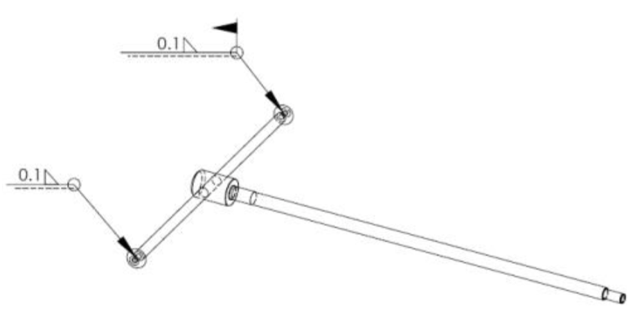
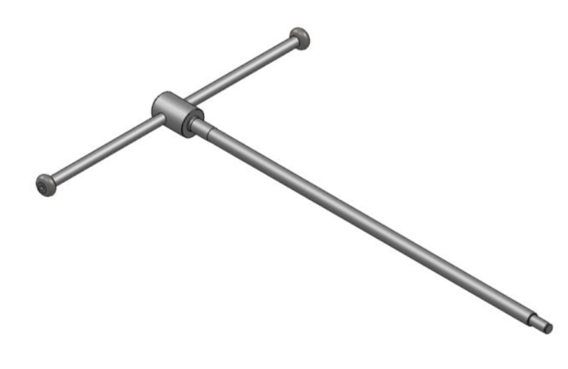
Step 1: Cut 16’’ work piece of 0.5’’ round bar. Turn it on a universal or CNC Lathe observing dimensions on drawing BD125-02.01.200.
Step 2: Cut two 0.5’’ work pieces of 1’’ round bar. Turn on a universal or CNC Lathe according to drawing BD125-02.01.200. Weld one of the parts to the rod observing the welding plan on Fig. 6.1.
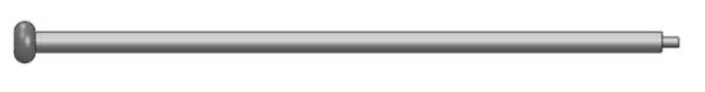
Step 3: Cut 25’’ work piece of 1 1⁄2’’ round bar. Turn the work piece on a universal or CNC Lathe and drill the hole according to dimensions on drawing BD125-02.01.001. Thread the obtained part from Step 2 at the already drilled hole in the Screw head. Proceed to welding the second head of the drive rod according to welding plan (Fig. 6.1). The complete assembly of screw is shown on the following figure.
7. Full Assembly Of The Bender.

- Frame support (BD125-00.00.300).
- Device frame (BD125-01.00.000).
- Screw support (BD125-02.00.100).
- Nut Tr 16x2 (BD125-02.00.001).
- Screw assy (BD125-02.01.000).
- Retaining ring 5160-47 S-0.473.
- Spring Washer A8 DIN 128.
- Screw M8x1.25x12 ISO 4762.
- Crank (BD125-00.00.001).
- Clevis pin 0.5x1.57 (BD125-00.00.005).
- Washer ANSI FW 0.5.
- Retaining splint DIN 94-3.2x20-C-St
- 13. Guiding wheel (BD125-00.00.002).
- Clevis pin 0.5x4.84 (BD125-00.00.004)
- Strickle 1-1/4 assy (BD125-00.00.100)
- Clevis pin 1x4.87 (BD125-00.00.003)
- Degrees divided disk (BD125-00.00.006)
- 18. Washer ANSI FW 1.
- Washer DIN 6902 – A3.
- Screw slotted M3x8 ISO 1207.
- Action lever strickle (BD125-00.00.200)
- Spring Washer A8 DIN 128.
- Screw M8x1.25x30 ISO 4762.
Before you start assembling the tube bender there is a few parts that have to be manufactured or bought. They are not included in the assembly guide above, because they are separate parts not included in the units described. Their numbers from Fig. 7.1 are: 4, 6, 7, 8, 9, 10, 11, 12, 13, 14, 16, 17, 18, 19, 20, 22, 23.
Step 1: Weld Frame support (1) and Device frame (2) together.
Step 2: Mount the Screw support (3) to Device frame (2) using the Washers (7) and Screws (8). Note the orientation (Fig. 7.1).
Step 3: Position the Nut (4) at the groove of Screw support (3) and thread the Screw assembly (5). Mount the Retaining ring (6).
Step 4: Thread the Nut (4) forward using the screw and position the hole of Crank (9) concentric to the hole of the nut. Mount the Clevis pin (10), Washer (11) and Retaining splint (12).
Step 5: Position the Guiding wheel (13) concentric to the holes of Little bushing and thread the Clevis pin (14). Mount the Washer (11) and Retaining splint (12). Try to rotate the wheel. If it doesn’t roll check the Retaining splint or use a thinner washer.
Step 6: Position the Strickle (15) and Degrees divided disc (17) concentric to the holes of Big bushing and thread the Clevis pin (16) through both. Mount the Washer (18) and Retaining splint (12). Try to rotate the Strickle (15).
Step 7: Mount the Washer (19) and thread Screw (20).
Step 8: Position Action lever strickle (21) concentric to the holes of Crank (9) and thread the Clevis pin (10). Mount the Washer (11) and Retaining splint (12).
Step 9: Thread the Nut (4) backward using the screw and position Action lever strickle (21) parallel (vertical) to Strickle (15). Mount the Washers (22) and tighten the Screws (23).
Congratulations!
You succeeded in assembling the Tubing Bender! Now send us some pictures so we can show off your build.
Tubing Bender Basics:
Your small workshop may use one of many different tube (pipe) bender styles, either hydraulic or mechanical. Generally, tube benders curve the tube along the horizontal plane. It is a good idea to bend the tube so that the weld is not along the top or bottom of the bend, but off-center. This adds strength to your frame bend.
Whether you purchase blueprints for your frame or design it yourself, you'll need to keep in mind that, when using the tubing bender to create frame curves, the tube may have to be bent slightly more than the degrees desired due to the fact that tubing has some spring back or memory. The over-bend will depend on the type of tubing being bend, the diameter, die radius, and tubing thickness. An example recently encountered when using a magnetic base dial angle finder to create a 90 degree bend, nearly 94 degrees were required when using the tubing bender to obtain a perfect 90 degree bend.
But you will almost never need a 90 degree bend for a chopper or bobber frame. You won't need a 90 degree bend on any of our frame plans.
If you design your own frame, keep in mind that safety comes first, so you'll need to be sure your geometry and design are going to properly support your motorcycle configuration. If you have never used a tubing bender before, you'll also want to practice some bends before actually beginning using the tubing bender to shape your frame. The process is not rocket science, but it is a critical part of your overall motorcycle or chopper safety and performance.
There are less expensive bow-type tubing benders which hold the tubing between a pair of rollers while the die presses in to form the bend, but these are not recommended because they do not compress the tube in such a way that the sidewall shape is true.
If you are really into frame building and plan to create frames from all three types of tubing and for various engines, you may well find that, with accessories, you may end up with over $1,000 invested in a good tubing bender with dies. Of course, if you wish, you can take your tubing to a professional motorcycle frame builder or fabrication shop and have your tubing bent to your design blueprint specifications.
Related Articles:
