Bike Lift Assembly Guide
This bike lift assembly tutorial is a step by step guide to building our motorcycle table lift. If you have any questions let us know. This should make the build easier for you.
Machinery and Tools Required For The Bike Lift Assembly:
- Plasma cutter (recommended).
- Universal or CNC lathe (recommended).
- Universal or CNC Milling machine (recommended).
- Bending machinery.
- Chop saw or Angle grinder.
- Drill press.
- MIG, TIG or Arc Welding.
- Welding equipment.
- Fitter's vise.
- Hammer, wrench set and tape measure.
- Drill set.
Bike Lift Build Materials List:
- Mild steel square tube – 2 X 2’’ (52 ft).
- Mild steel sheet – 0.25’’ thickness (97 ft2), 0.5’’ thickness (30 in2), 0.625’’ thickness (127 in2).
- C channel – 2 X 2’’ (11 ft).
- Tread plate - 0.25’’ thickness (175 ft2).
- Mild steel round bar – ½’’ (45 in).
Bike Lift Purchased Parts:
- (22) HBOLT 0.375-16x1x1-S.
- (22) HNUT 0.375-16-D-N.
- (44) Washer Narrow FW 0.375.
- (4) Shepherd Caster – CPS 40156 TZ – R0181 (KK) TB.
- (1) Safety lock pin (Clevis pin) – 0.5x6.25’’.
- (1) Clevis pin – 0.5x7’’.
- (8) Clevis pin – 0.5x5’’.
- (3) Clevis pin – 0.5x3’’.
- (1) Clevis pin – 0.5x2’’.
- (14) Retaining splint DIN 94-3.2x20-C-St;
- (1) Hydraulic jack – 8 Ton, Harbor freight item #36397.
1. Assembling The Base Assembly.
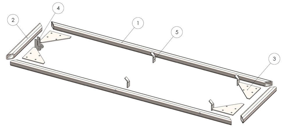
Parts:
1. Square tube – 84.
2. Square tube – 24.
3. Corner-Gusset.
4. Pin plate.
5. Stopper.
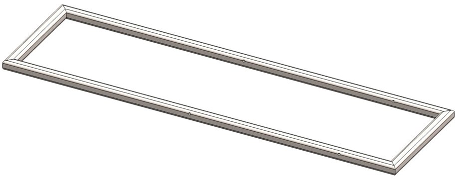
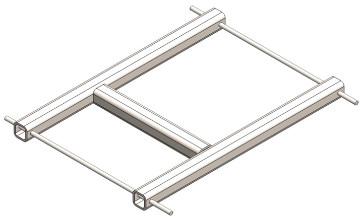
Step 1: Cut two 84'' long pieces of 2X2'' square tube. Miter cut at 45 deg. Drill all of the holes needed for the pins on the square tubes. Make sure that they are all in line and have a positional tolerance 1/16" or better with each other. Also make sure that the holes are perpendicular to the tube's plane.
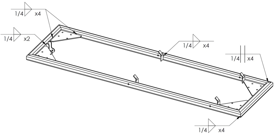
Step2: Cut two 24' long pieces of 2X2" square tube and shape the ends at 45 deg. Arrange the profiles in frame on a flat working surface according to montage plan (Fig. 1.2). Make sure that the holes are aligned properly and complete the welds observing the welding plan on Fig. 1.1.
Step 3: Cut four Corner-Gussets with the corresponding size. Drill the holes where the caster wheels will be mounted. Align the plates in the middle of the square profile and complete the welds according to the welding plan.
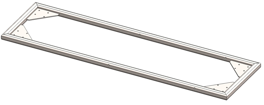
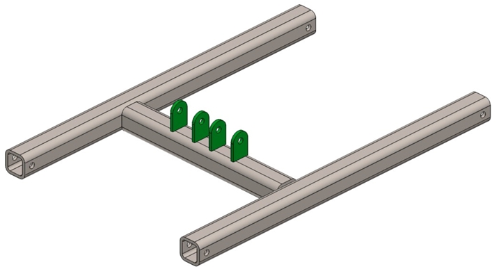
Step 4: Cut two 2x4" pieces of 0.25" thick mild steel sheet. Machine the overall dimensions and drill the hole. Weld the plates in the middle of the short square profile observing the dimensions on the drawing. Note the orientation of the side holes in the long square profile.
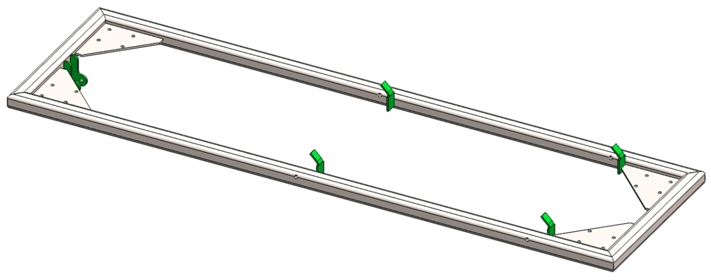
Cut to size the stopper plates and execute the bends. Weld them in place observing the drawing.
2. Assembling The Platform.
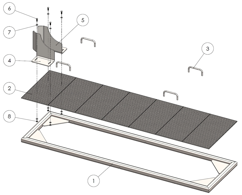
Parts:
- Base assembly.
- Tread plate.
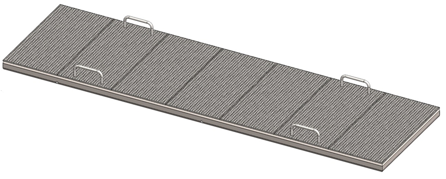
- Handle.
- LH Choke.
- RH Choke.
- HBOLT 0.375-16x1x1-S.
- Washer Narrow FW 0.375.
- HNUT 0.375-16-D-N.
Step 1: Repeat Step 1 to Step 3 from the Base assembly directions except drilling the holes in the corner-gusset (Caster wheel mounting holes). Same assembly, but rotated and used for platform. Same mounting pivoting holes. Drill holes prior to welding together in order to maintain positional tolerance mentioned in the plans.
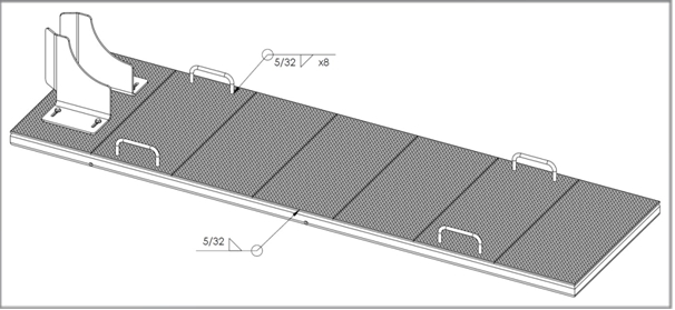
Step 2: Arrange the tread plates on flat working surface. Place the platform frame over the treaded plates. Watch for proper orientation and alignment of the frame.
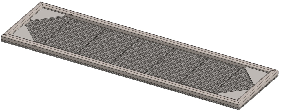
Complete the welds on the underside, see welding plan (Fig. 2.1). Be sure to weld the tread plate that holds the choke securely. Also be sure to weld the handle plates securely so that they can be used for pushing, pulling, and securing the bike. Other tread pieces can be tack welded only, since they will be top loaded only.
Step 3: Proceed to welding the handles to the both sides of the tread plates specified in the plans. Observe the welding plan on Fig. 2.1.
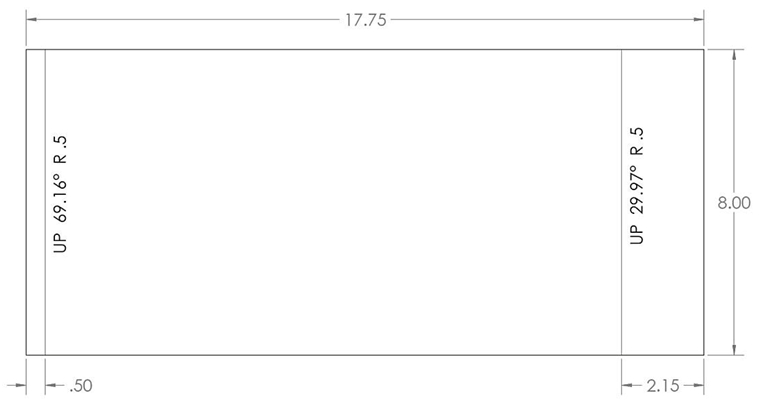
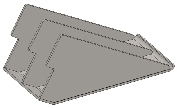
Step 4: Cut two blanks out of 0.25" thick mild steel sheet. Bend according to the guidelines and specified radiuses. Note that there is a left and right chokes. Drill holes into the tread plate and bolt on the parts as shown in montage plan (Fig. 2.2).
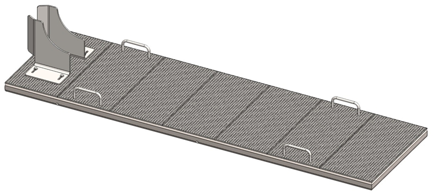
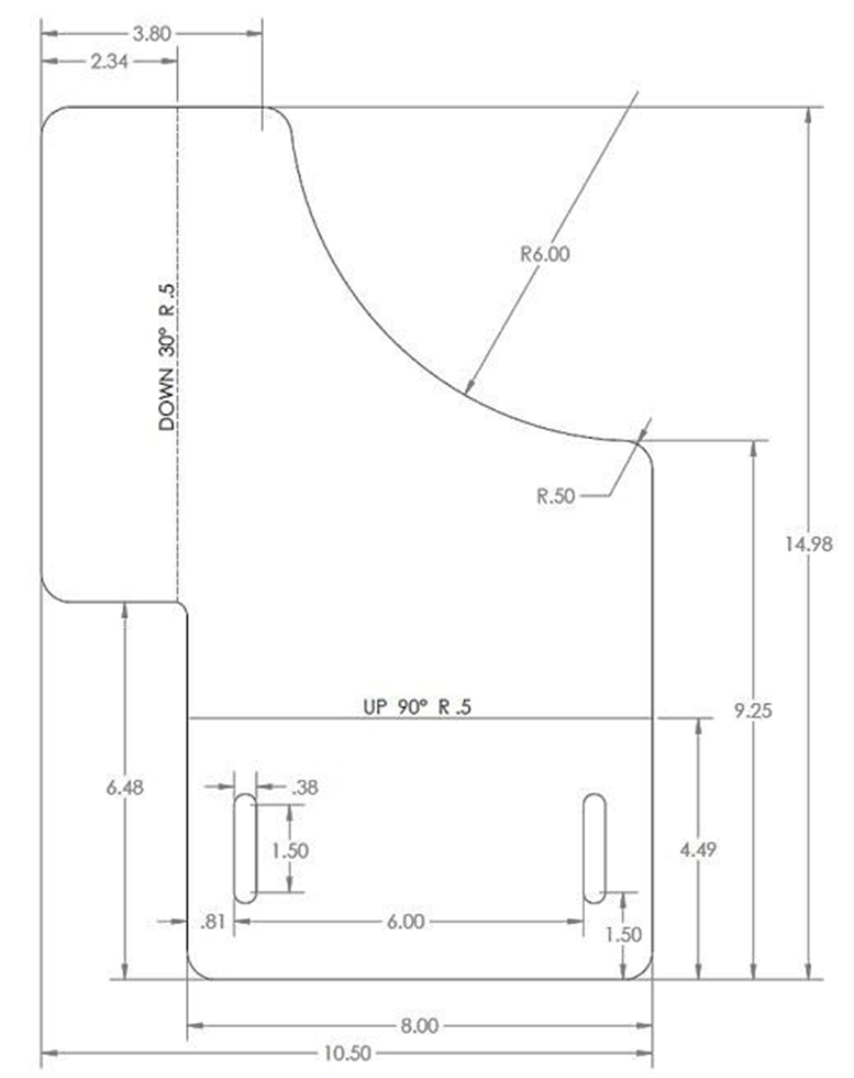
The slots will allow adjustment of the chokes for the appropriate tire size. A combination of holes into the tread plate can be drilled for adjusting in longitudinal direction.
3. Assembling The Fork Assembly.
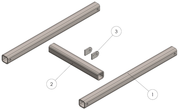
Parts:
- Square tube – 30.
- Square tube – 16.
- Pin plate.
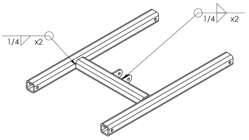
Step 1: Cut two 30" and one 16" long pieces of 2x2" square tube. Drill the holes needed for the pins on the square tubes. Lay the parts out on a flat working surface. Use long rod to hold the tubes in correct position relative to each other. Positional tolerance is critical or there may be friction and/or jamming that may occur if the holes are not in line. Fillet weld ¼’’ all around the tube (Fig.3.1).
Step 2: Cut two pin plates according to the drawing and drill the holes. Weld them in the middle of the 16" tube as shown in montage plan. Observe dimensions in the drawing.
Step 3: Repeat step 1 to assemble the second fork. Cut four pin plates and weld them in place according to the drawing. The exact location is given in the plans on page 1. Use pins or rods to ensure that the holes are not in line.
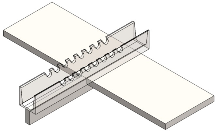
4. Assembling The Safety Lock.
Parts:
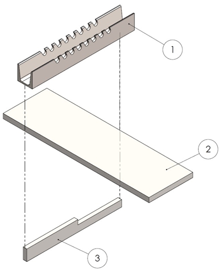
- C Channel.
- Flat plate.
- Support gusset.
Use large welds when putting these components together and also when attaching to the base. This component takes a lot of load in the event of failure and should be made extremely rigid.
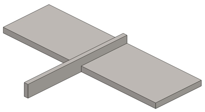
Step 1: Cut the flat plate and support gusset parts with dimensions given in the plans. Arrange them as shown on the next picture and complete the weld according to the welding plan (Fig. 4.1).
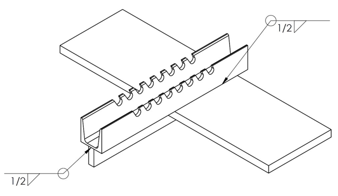
Step 2: Cut a 14" long piece 2x2" C channel. Drill the 0.5" holes first and then cut out the additional material. The grooves on both sides of the channel need to be identical to each other in order to distribute the load evenly along the channel. Turn upside down welded plate and gusset and align the front end of the C channel with the support gusset, the other end of the C channel have to jut out. Pay attention for orientation of the groves. Proceed to welding the components together. Observe the welding plan on Fig. 4.1.
5. Assembling The Rear Choke.
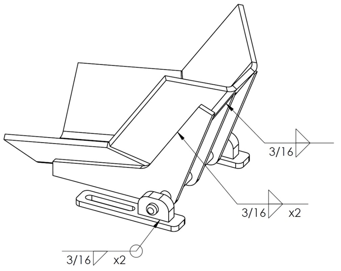
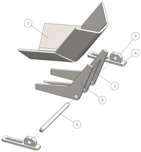
Parts:
- Choke plate.
- Small gusset.
- Large gusset.
- Base plate.
- Eyelet.
- 1/2’’ pin (Clevis pin).
Step 1: Cut the blank for bending the choke plate with dimensions given in the plans. Bend the two parallel longer bends first. Second smaller bend can be done using clamps. This bend doesn't need to be sharp. Large round bend will be fine as long as it can fit up with the gussets.
Step 2: Cut the gussets out of 0.25" thick mild steel sheet and drill the holes for the pins. Weld center gusset first using a fillet weld, see welding plan on Fig. 5.1. Use pin to locate the other two gussets prior to welding. Maintain parallelism between the plates in order to insure proper function.
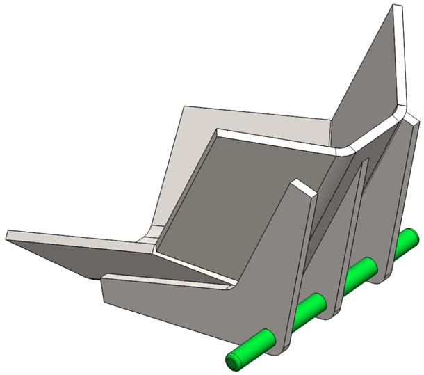
Step 3: Cut base plates and eyelets out of mild steel sheet. Machine the slots and drill the holes for the pin. Arrange both parts and complete the welds.
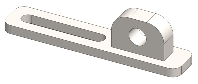
Step 4: Place both base assemblies on a flat working surface. Position the holes of the gussets concentric to the holes in the eyelets and thread the pin. Lock the pin with retaining splint to keep it in place during normal use.

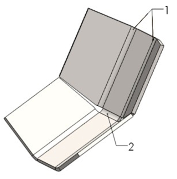
6. Assembling The Ramp.
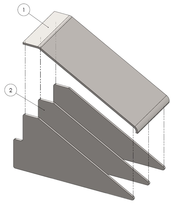
Parts:
- Ramp sheet.
- Ramp gusset.
Step 1: Cut the blank for bending the ramp sheet and bend both 0.5" radiuses.
 Click for larger image.
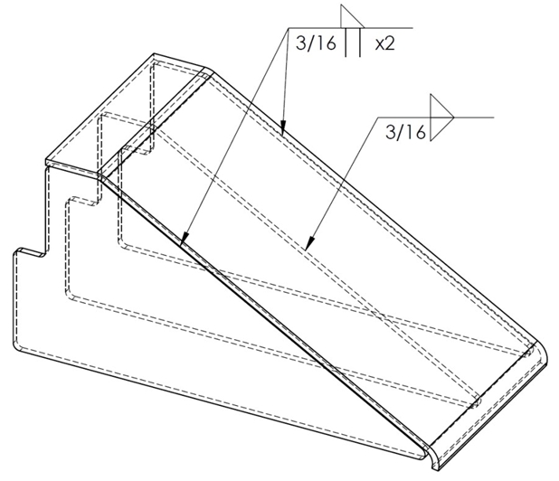
Step 2: Position the bended sheet upside down on a flat working surface. Arrange the gussets over the sheet and tack weld them in place. Use welding fixtures to ensure the proper position. Make sure that they perpendicular to the sheet. Check alignment and complete the welds according to the welding plan (Fig. 6.1).
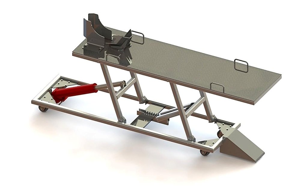
7. Assembling The Whole Bike Lift.
Step 1: Start assembling the Bike lift with attaching the caster wheels to the base. Turn the base assembly (1) upside down on a flat working surface. Note the position of the holes for the pins. Attach the caster wheels (2) to the gussets using the bolts (3), washers (4) and nuts (5). Make sure that they are tightened well. Roll over the assembled components in normal position.
Step 2: Position the safety lock assembly (6) in the exact place specified in the plans (Page 1). Use large welds when attaching this component to the base. Note for orientation of the grooves.
Step 3: Proceed to mounting the hydraulic jack (7) to the base assembly (1). Position the mounting hole of hydraulic jack concentric to the holes in the pin plates and thread the clevis pin (8). Lock with retaining splint (9).
Step 4: Continue with mounting the front and rear fork assemblies (10, 11) to the base assembly (1). Position the components in place and thread the clevis pins (12). Lock with retaining splints (13).
Step 5: Attach the other side of the hydraulic jack (7) to the pin plates of the fork assembly (10). Align the holes of the components, thread the clevis pin (14) and lock in position with retaining splint (15).
Step 6: Cut two 16" long pieces of 2x2" square tubes and drill the holes for the pins according to the plans. Mount the safety square tubes (16) to the fork assembly (11) using clevis pins (17) and retaining splints (18). Position the holes on the other end of the safety tubes concentric each other and mount the safety lock pin (19) and retaining splint (20).
Step 7: Proceed to mounting the platform. Place the platform (21) over the base assembly (1). Make sure that it is in proper position. Align the side holes in the frame with holes in the fork assemblies (10, 11). You may need to raise the end of the fork assemblies a little bit. When the holes are concentric each other, thread the clevis pins (22) and lock with retaining splints (23).
Step 8: Place the rear choke (24) on the platform. Mark the exact place specified in the plans and drill a holes in the tread plate. Use bolts (25), washers (26) and nuts (27) for attaching the component. Slots in the base plates allows you to adjust the choke position for different tire sizes. Make sure that the bolts are tightened well before loading the bike.
Step 9: Weld ramp assembly (28) to the square tube.
CONGRATULATIONS!
You finished assembling the Bike Lift!