Bike Trailer Assembly Guide
This tutorial shows you how to build the single motorcycle trailer from the plans which are available on this page.
Machinery and Tools Required For The Bike Trailer Assembly:
- Chop saw or Angle grinder.
- Drill press.
- MIG, TIG or Arc Welding.
- Welding equipment.
- Fitter's vise.
- Hammer, wrench set and tape measure.
- Drill set - 0.2" - 0.75".
- Plasma cutter (recommended).
- Universal or CNC lathe (recommended).
- Universal or CNC Milling machine (recommended).
- Bending machinery.
Bike Trailer Build Materials List:
- Mild steel square tube - 1.75" X 1.75" t=0.25" (41 ft).
- Mild steel sheet - 0.125" thickness (140 ft2).
- Mild steel square bar - 2 X 2 1/2" (16 in).
- 1.5" tubing (31 ft).
- 1.25" tubing (12.5 ft).
- Plywood or steel sheet (321 ft2).
- Sailcloth (~170 ft2).
Bike Trailer Purchased Parts:
- (4) Bushing 1/2" ID x 1" OD x 1.75" Length.
- (8) Wing screw 1/2 - 20x1.
- (4) HBOLT 0.5-13x3x1.25-S.
- (3) Round Head BOLT 0.5-13x2.75x1.25-S.
- (1) Round Head BOLT 0.5-13x4.5x1.25-S.
- (8) HNUT 0.5-13-D-N.
- (12) Washer Narrow FW 0.5.
- (1) AL-KO braked axle S 19.
- (1) Coupling.
- (1) Supporting wheel.
- (2) Rim 5J15, offset 0".
- (2) Tire 195/70T15.
- (2) Fender.
- (1) Electric and lighting system.
1. Assembling The Bike Trailer Chassis.
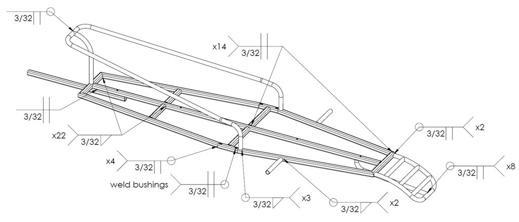 Fig. 1.1 Chassis welding plan Fig. 1.1 Chassis welding plan |
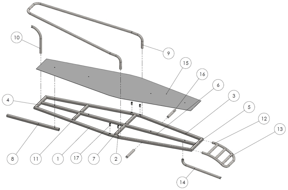 Fig. 1.2 Chassis montage plan Fig. 1.2 Chassis montage plan |
Parts:
- Front side element (tm120x34.01.01).
- Side element (tm120x34.01.02).
- Bike side element (tm120x34.01.03).
- Front element (tm120x34.01.04).
- Rear frame element (tm120x34.01.05).
- Long beam (tm120x34.01.06).
- Middle element (tm120x34.01.07).
- Drawbar (tm120x34.01.08).
- Protective bar (tm120x34.01.09).
- Support pipe (tm120x34.01.10).
- Reinforcement (tm120x34.01.11).
- Rear bridge (tm120x34.01.12).
- Pipe (tm120x34.01.13).
- Bottom support (tm120x34.01.14).
- Plate (tm120x34.01.15).
- Lights support (tm120x34.01.16).
- Bushing (tm120x34.01.17).
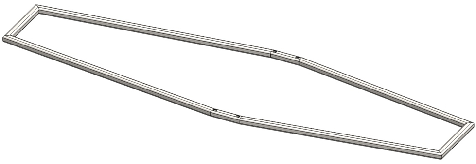
Step 1:
Cut part numbers from tm120x34.01.01 to tm120x34.01.05 which are forming the basic frame of the chassis. Cut the exact the angles on the ends and drill the 1" holes for the bushings in part number tm120x34.01.02. Arrange the pieces on a flat working surface according to the assembly drawing tm120x34.01.00. Tack weld them in place. Check alignment and across dimensions. If there is no gaps proceed to welding the frame observing the welding plan (Fig. 1.1).
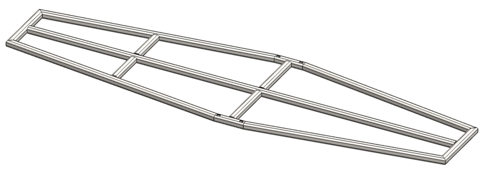
Step 2:
Cut part numbers tm120x34.01.06, tm120x34.01.07 and tm120x34.01.11. Arrange the parts as shown (see drawing tm120x34.01.00). Tack weld them in place. Check alignment and complete the welds.
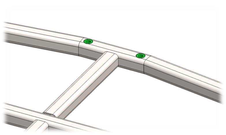
Step 3:
Put the bushings in the already drilled holes and weld them on both sides. Keep the inner diameter clear from welding dribble.
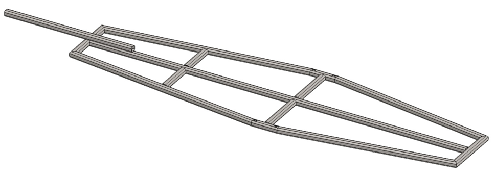
Step 4:
Cut the drawbar element tm120x34.01.08. Position it on the frame as shown on the picture. Comply the 25" dimension (see the assembly drawing tm120x34.01.00) and complete the welds.
Step 5:
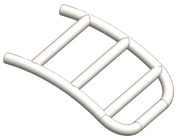
Cut part numbers tm120x34.01.12 (~55" length) and tm120x34.01.13 (three 15" long pieces). Bend the rear bridge observing the dimensions on the drawing. Start from bending the R4" radiuses and then proceed to bending the R30" and then cut the proper size. Notch the ends of the pipes and position them crossly to the already bended rear bridge as shown on the picture. Distribute equally the distance between the pipes. Use welding fixtures to ensure the position and complete the welds according to the welding plan.
Step 6:
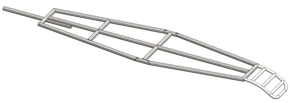
Weld the rear bridge assembly to the frame (see montage plan, Fig. 1.2).
Step 7:
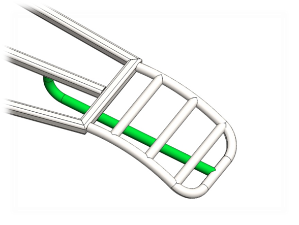
Cut part number tm120x34.01.14, the bottom support (~33" long pipe). Bend according to the drawing and notch the long side. Put the part in right position and complete the welds.
Step 8:
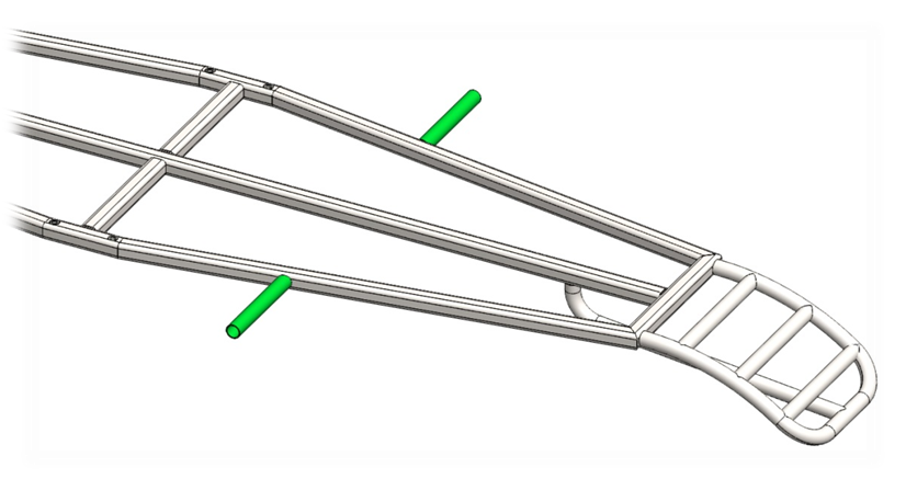
Cut the lights support pipes, part number tm120x34.01.16, and shape the 9º angle. Position the pieces on both sides of the frame complying the 32.7" dimension. Complete the welds according to the welding plan on Fig. 1.1.
Step 9:
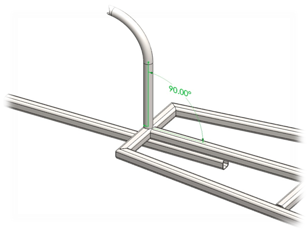
Cut part number tm120x34.01.10, ~25’’ long pipe. Bend according to the drawing and notch the short end. Position the part on its place on the frame as shown on the next picture. Ensure the perpendicular position of the pipe and direction of the back. Tack weld in place. Check alignment again and complete the welds according to the welding plan (Fig. 1.1).
Step 10:
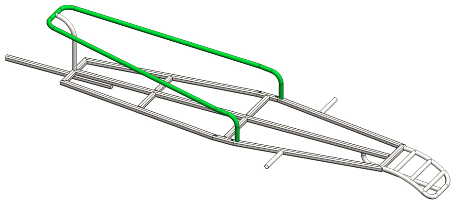
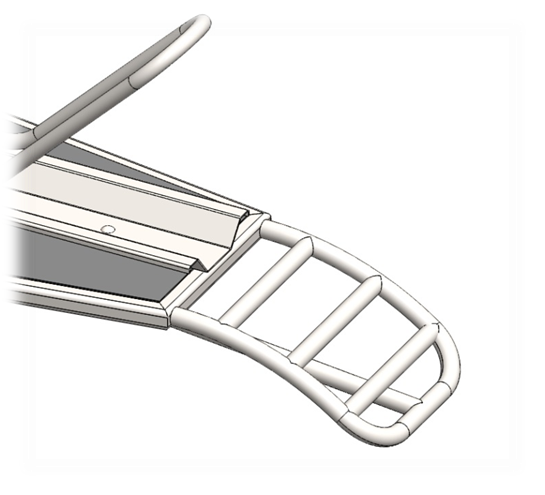
Cut part number tm120x34.01.09, ~190’’ long pipe. Start bending inwards, the R4" and R4.2". Finally bend the inner radiuses complying the 33.5" dimension. Position the part observing the assembly drawing tm120x34.01.00 and complete the welds.
Step 11:
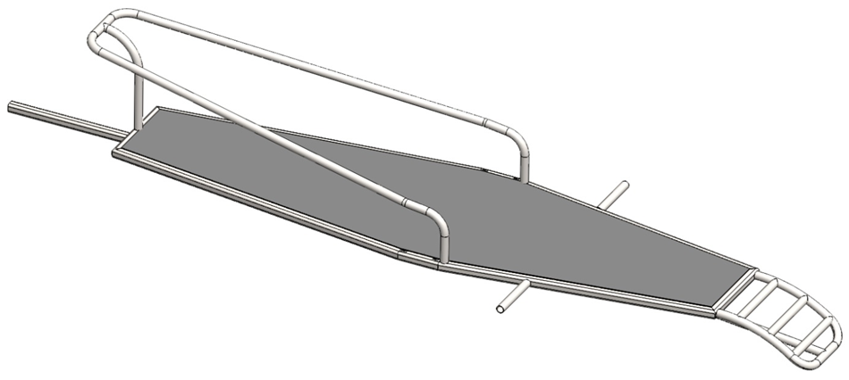
Cut a piece of plywood or steel sheet that will fit to the bottom of the chassis. Mount the plate using screws or welding depending on the material.
2. Assembling The Bike Rail.
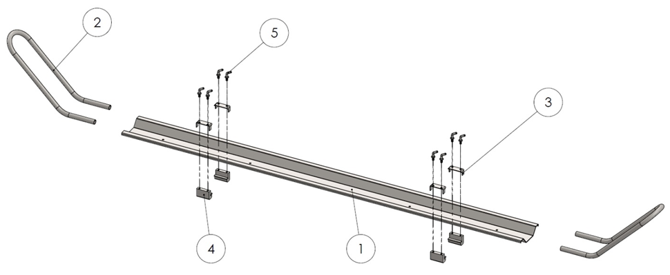 Fig. 2.1 Bike rail montage plan
Parts:
- Platform (tm110x70.03.01).
- Bended pipe (tm110x70.03.02).
- Plate (tm110x70.03.03).
- Fixing part (tm110x70.03.04).
- Hand screw (tm110x70.03.05).
Step 1:
Cut a 12.66 x 120’’ piece of 0.125’’ thick mild steel sheet. Start bending inwards according to the blank on tm110x70.03.01 drawing. Drill the 0.5" holes.
Step 2:
Cut two 75" long pieces of 1.25" pipe. Start from bending the 4.375" radiuses according to the drawing (tm110x70.03.01). Then proceed to bending the inner 3.73" radius.
Step 3:
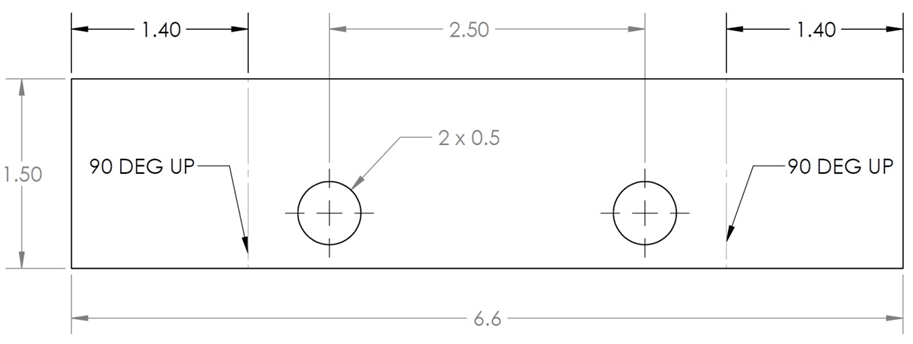
Cut four 1.5x6.6" pieces of 0.125" mide steel sheet and drill the holes. Execute the bends and then proceed to milling the R0.625", otherwise both sides will not touch the pipe when are tightened.
Step 4:
Cut four 3.75" long pieces of 2x2 1/2" mild steel square bar. Mill according to the drawing (tm110x70.03.04) and drill the holes.
Step 5:
Lay the platform on a flat working surface. Put in the side fold in the 0.125" slot of the fixing part. Position the plates as shown in montage plan and screw the hand screws, but don't tighten. Repeat for the rest three fixing assemblies.
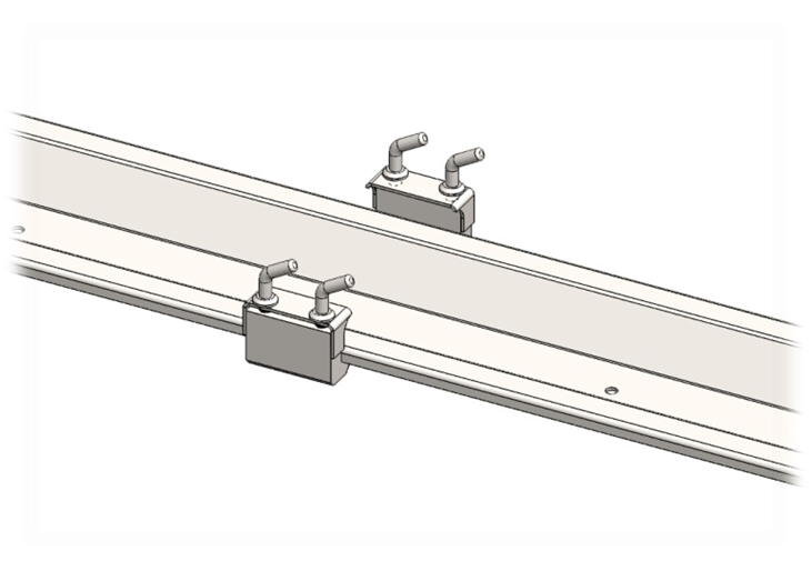
Step 6:
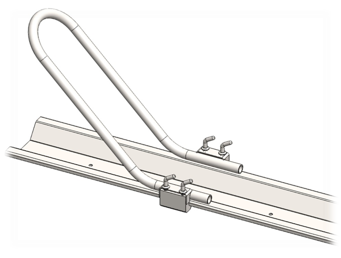
Position the bended pipes in its place on the platform and tighten the screws.
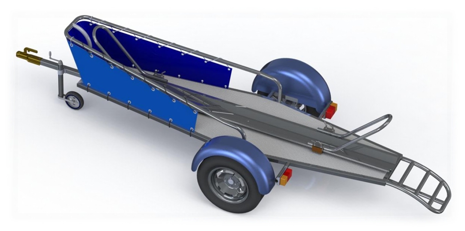
3. Assembling The Bike Trailer.
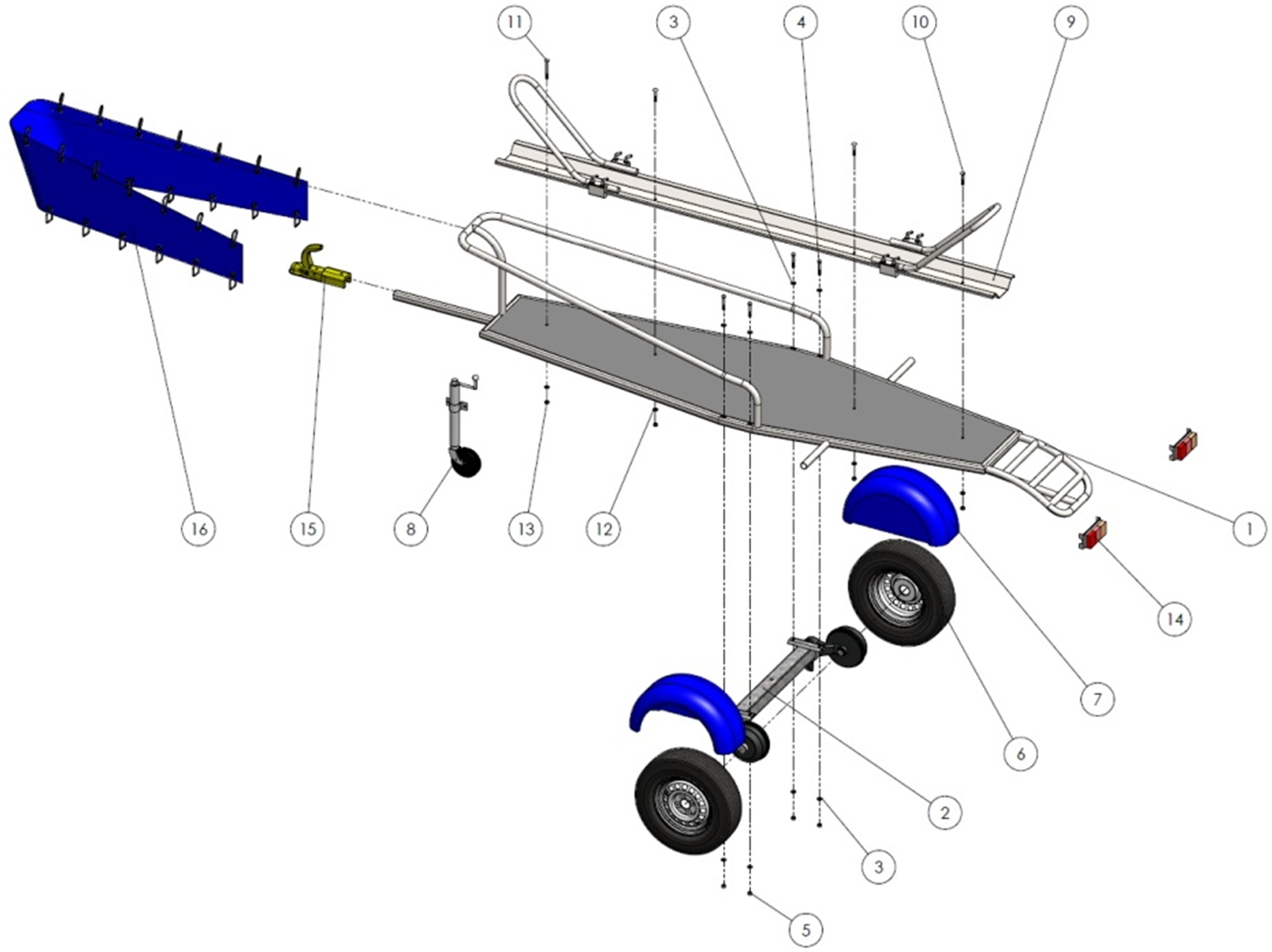 Fig. 3.1 Bike trailer montage plan
Step 1:
Turn upside down the chassis frame (1), so you will be comfortable to mount the axle (2). Position the holes of the axle concentric to the holes of the chassis. Thread the bolts (4) and washers (3) upside down, so when the trailer is in working position they will not fail off if a problem occurs. Tighten using the washers (3) and nuts (5).
Turn the chassis with the axle in its normal position.
Step 2:
Lift up the chassis using a jack or crane and mount the wheels (6). Proceed to mounting the fenders (7).
Step 3:
Mount the supporting wheel (8) observing the assembly drawing tm120x34.00.00. For mounting method of the supporting wheel see manufacturer's recommendations. Lift up the supporting wheel to align the trailer.
Step 4:
Put the bike rail assembly on the chassis. Align the platform with the rear side of chassis as shown on the picture. Mark the positions of the holes on the plywood and remove the bike rail. Drill a through holes in chassis and mount the bike rail (9) using the Round head bolts (10, 11) washers (12) and nuts (13).
Step 5:
Install the electric and lighting system (14) depending on manufacturer's recommendations.
Step 6:
Mount the coupling (15) and sailcloth (16) to the chassis according to montage plan (3.1).
CONGRATULATIONS!
You finished assembling the Bike Trailer!