
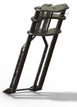
How To Build Springer Forks!
This guide to building springer forks will help you build our front end from the plans we created.
Some advanced fabricators may be able to use this springer for building guide alone, but most of us will need the plans.
This step by step tutorial is designed so that a novice could navigate their way to a nice set of forks.
But as always when it comes to fabricating motorcycle and automobile parts you should double check your build with an experience fabricator and/or bike builder.
Tools and Machinery For The Springer Fork Build:
- Chop saw or Angle grinder.
- Drill press.
- MIG, TIG or Arc Welding.
- Welding equipment.
- Fitter’s vise.
- Hammer, wrench set and tape measure.
- Drill set.
- Plasma cutter (recommended).
- Universal or CNC Lathe (recommended).
- Universal or CNC Milling machine (recommended).
Materials List For Springer Front End Fabrication:
- 1’’ DOM tubing – (60 in).
- 1.5’’ DOM tubing – (60 in).
- Mild steel sheet – 0.75’’ thickness (6 ft2); 0.5’’ thickness (16 ft2).
- 1 ½’’ Steel round bar (5 in); 1’’ Steel round bar (6 in); ½’’ Steel round bar (13 in).
- (1) Hex Bolt 0.75-9.5x1x1-S.
- (2) Hex Bolt 0.5-13x1x1-S.
- (2) Round Head Bolt 0.75-10x1x1-S.
- (3) Hex Nut 0.75-10-D-S.
- (2) Hex Nut 0.5-13-D-S.
- (2) Clevis pin 0.5 X 1.75’’.
- (2) Clevis pin 0.5 X 1.5’’.
- (4) Retaining splint.
- (2) Spring - ID=1.151 min, WD=0.104, L=3 in.
- (2) Spring - ID=1.625 min, WD=0.156, L=4.75 in.
1. Springer Front Fork Assembly:

Parts:
- Top plate.
- Steering head bolt.
- Hex Nut 0.75-10-D-S.
- Middle plate.
- Bottom plate.
- Spring crown plate.
- Top spring.
- Main spring.
- Spring base plate.
- Spring tubes.
- Main fork tubes.
- Axle plates.
- Axle rod.
- 1 ½’’ Solid machined rod.
- 1’’ Solid machined rod.
- ½ x 1.75’’ Pin.
- ½ x 1.5’’ Pin.
- Retaining splint.
- Hex Nut 0.5-13-D-S.
- Hex Bolt 0.5-13x1x1-S.
- Hex Nut 0.75-10-D-S.
- Round Head Bolt 0.75-10x1x1-S.
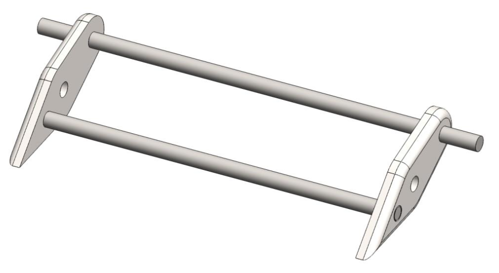
2. Assembling The Main (Stationary) Fork:
Parts:
- Top plate.
- Steering head bolt.
- Middle plate.
- Bottom plate.
- Hex Nut 0.75-10-D-S.
- Main fork tubes.
- 1 ½’’ Solid machined rod.
- Hex Nut 0.75-10-D-S.
- Round Head Bolt 0.75-10x1x1-S.
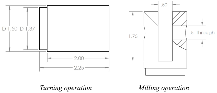
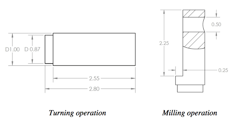
Step 1: Cut two 2.5’’ pieces of 1 ½’’ steel round bar. Turn on universal or CNC lathe according to the drawing. Mill the slot and drill the hole (the drawings are for example, dimensions can be changed, but keeping the overall size and the hole position).
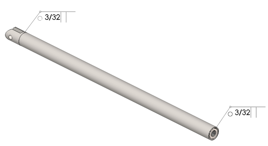
Step 2: Cut two 28’’ long pieces of 1.5’’ DOM tubing. Take one piece and position it on a flat working surface. Weld the already machined Solid rod on the one end of the Main fork tube and 0.75 Hex Nut on the other end (see Fig. 2.2). Repeat for the second piece.
Step 3: Cut two 5 x 15’’ pieces of 0.5’’ thick mild steel sheet. Machine the top and bottom plate according to dimensions in the plans. Thread the Steering head bolt through the center hole of the Top plate and screw a 0.75’’ Hex nut. Thread the bolt also through the Bottom plate and screw a second nut. Perform the 8’’ dimension between the plates and tighten the nuts. Try to keep the holes concentric.
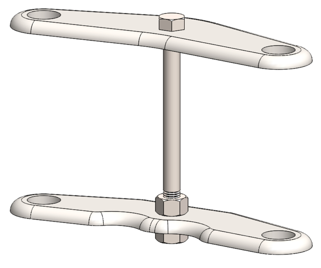
Step 4: Cut a 5 x 15’’ piece of 0.75’’ thick mild steel sheet. Machine the Middle plate according to the plans.
Step 5: Place the plate assembly on a flat working surface. Take the Main fork tube assemblies from Step 2 and thread them through the holes of the bottom plate. Holding the Middle plate between the Top and Bottom plate thread the tubes to the upper face of the Top plate. Use an additional 0.5’’ rod pushed through the holes on the other side of the main fork tubes. Screw the 0.75 Round head bolts. If these holes are not aligned properly the entire assembly will not function smoothly and correctly.
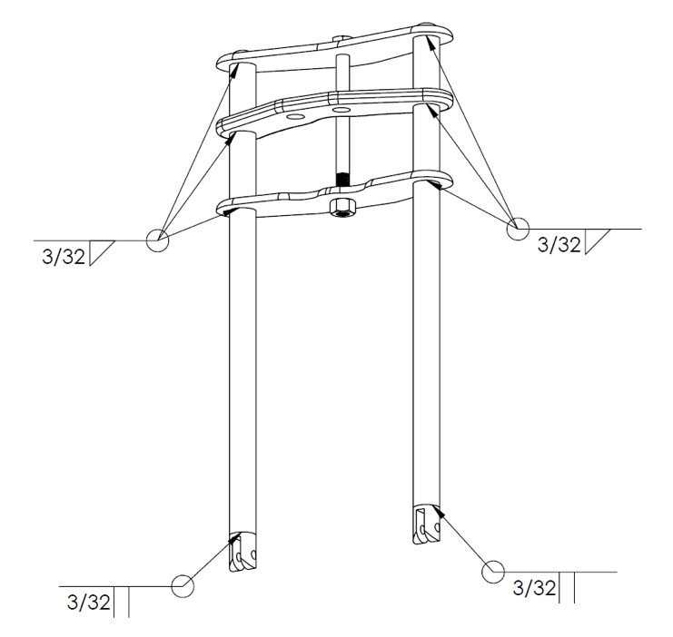
Step 5: Perform the 3.25’’ dimension between the Top and Middle plate using welding fixtures (see the drawings). Tack weld the components and check the alignment. If everything is properly aligned complete the welds observing the wilding plan on Fig. 2.1.
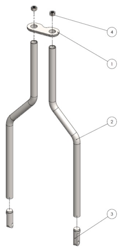
3. Assembling The Springer (Moveable) Fork:
Parts:
- Spring base plate.
- Spring tubes.
- 1’’ Solid machined rod.
- Hex Nut 0.5-13-D-S.
Step 1: Cut two 3’’ pieces of 1’’ steel round bar. Turn on universal or CNC lathe according to the drawing. Mill the lowering 0.25 x 2.25’’ and drill the 0.5 hole (the drawings are for example, the dimensions can be changed, but keeping the overall size and the hole position).
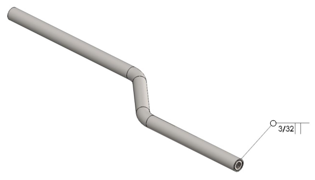
Step 2: Cut two 30’’ long pieces of 1’’ DOM tubing. Bend according to the drawing and then cut the proper 27.25’’ length. Make sure the top and bottom faces are parallel. 14
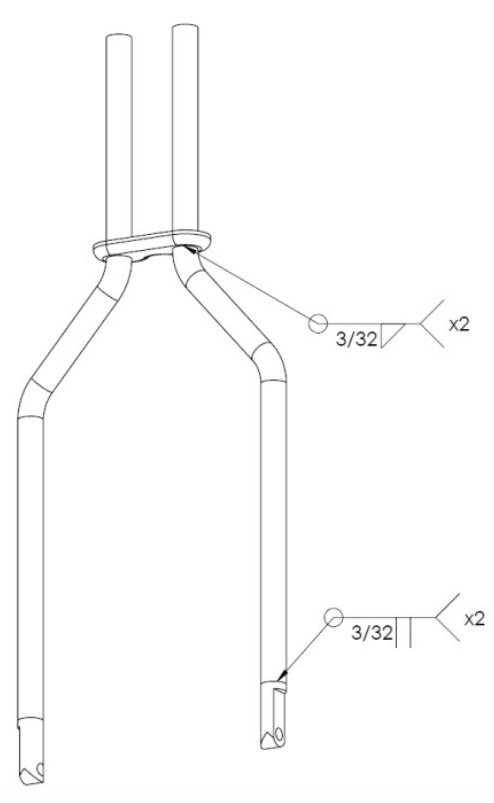
Step 3: Take two 0.5 Hex nuts and weld them to the upper side of the Spring tubes as shown on the picture.
Step 4: Cut two 2.25 x 5’’ pieces of 0.5’’ thick mild steel sheet. Machine the Spring crown plate and Spring base plate according to dimensions in the plans.
Step 5: Position the already machined 1’’ solid rods on a flat working surface. Thread an additional 0.5’’ rod through the holes to ensure the concentric position of the holes. Position the Spring base plate at 9.25’’ distance from the top face of the spring tubes. Tack weld the elements in place. Check that they are properly aligned, otherwise the entire assembly will not function smoothly and correctly. Proceed to welding the assembly observing the welding plan (Fig. 3.1).
4. Front Axle Plate Assembly.
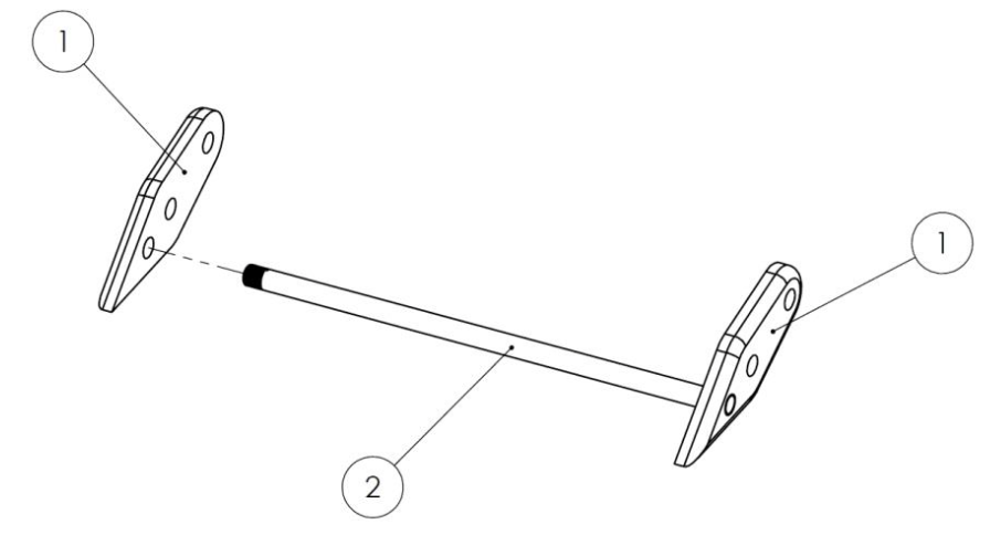
Parts:
1. Front axle plates. 2. Axle rod.
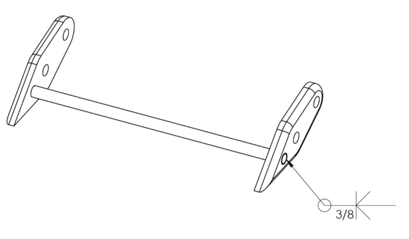
Step 1: Cut two 2 x 6’’ pieces of 0.5’’ thick mild steel sheet. Machine the Axle plate parts according to dimensions in the plans.
NOTE: One of the Axle plates have to be welded to the Axle rod, and another one have to be screwed, so drill one of the holes with proper diameter and machine the thread.
Step 2: Cut a 13’’ long piece of 1⁄2’’ Steel round bar. Machine a proper thread on the one side of the rod. Screw to the taped Axle plate.
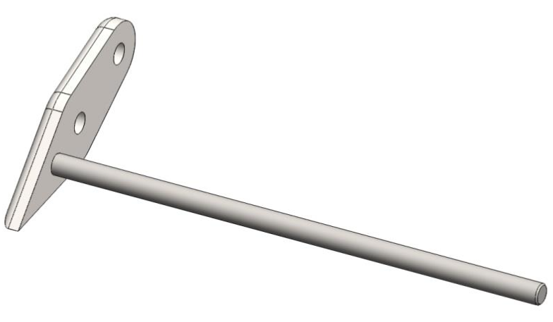
Step 3: Fit in the other side of the Axle rod through the hole of the not threaded Axle plate. Align the holes with additional 0.5’’ rod. Make sure the axle is perpendicular and aligned properly. Alignment is critical for proper steering. Make a secure welded connection according to the welding plan (Fig. 4.1).
NOTE: The threads should be oriented such that when the motorcycle is rolling forward, the threads should be tightening, not loosening direction. Orientation of the thread correctly is important in order to minimize any chance of the axle rod being loosened.
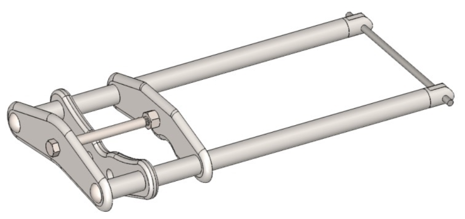
5. Assemble The Springer Forks.
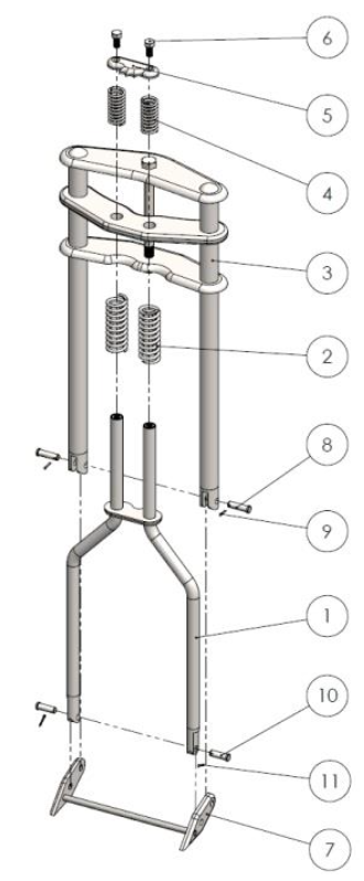
Parts:
- Springer fork assembly.
- Main spring.
- Main fork assembly.
- Top spring.
- Spring crown plate.
- Hex Bolt 0.5-13x1x1-S.
- Axle plates assembly.
- 1⁄2 x 1.75’’ Pin.
- Retaining splint.
- 1⁄2 x 1.5’’ Pin.
- Retaining splint.
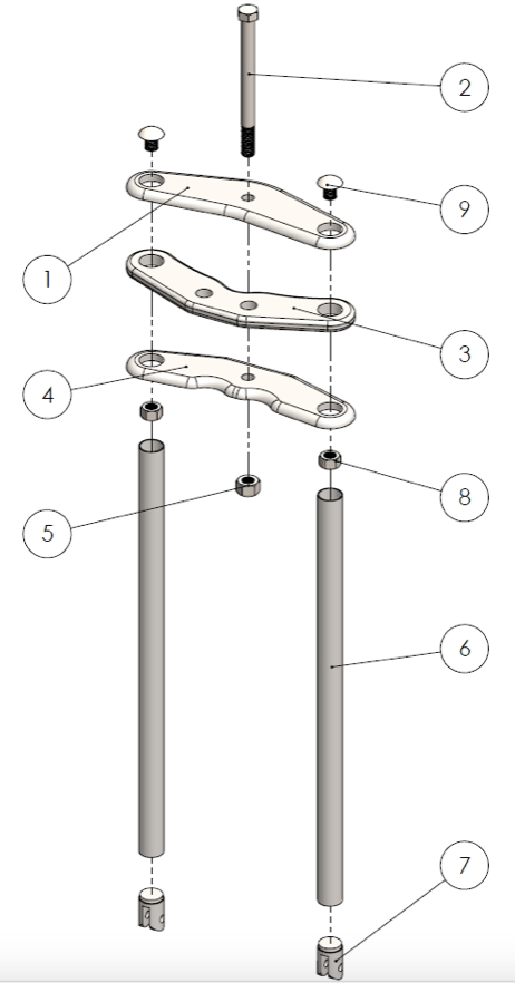
Step 1: Take the Springer fork assembly (1) and fit in the two Main springs (2).
Step 2: Thread the springer tubes through the corresponding holes in the Main fork assembly (3), see montage plan (Fig. 5.1). Fit in the Top springs (4).
Step 3: Position the Spring crown plate (5) in proper position and screw with the two 0.5 Hex bolts (6).
Step 4: Take the Axle plates assembly (7) and position the 0.5’’ holes concentric to the holes of the Main fork assembly (3). Mount the 0.5 x 1.75’’ Pins (8) and lock with Retaining splints (9).
NOTE: The montage scheme with pins and splints is for example and can be changed depending on the needs.
Step 5: Position the center holes of the Axle plates assembly (7) concentric to the holes of the Springer fork assembly (1). Fit in the 0.5 x 1.5’’ Pins (10) and lock with Retaining splints (11).
Step 6: Apply paint / Surface finish as desired.
Step 7: Remove the Steering head bolt and attach fork to bike frame.
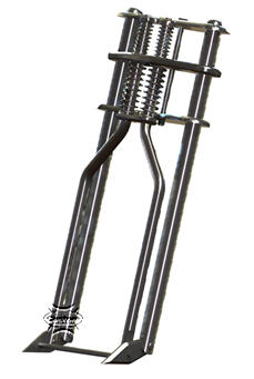
Congratulations!
Springer Fork Build Accomplished!
