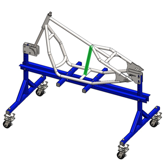
Rigid Bobber Frame Assembly!
This rigid bobber frame assembly guide is a step by step tutorial that shows you how to build the frame from the plans which are available here.
The frame jig in this tutorial is the one that you can build from the plans which are available here. Otherwise any quality jig will do the job.
Tools You'll Need For The Rigid Bobber Frame Build:
- Frame jig (recommended).
- Chop saw or Angle grinder.
- Tubing bender.
- Tube notcher and tube notching accessories.
- MIG, TIG or Arc Welding.
- Fitter’s vise.
- Hammer, wrench set, tape measure, caliper.
- Drill press.
- Drill set.
Materials List:
- 1.25’’ ERW tubing (26 ft).
- Mild steel sheet – 1’’ thickness (120 in2).
- Mild steel sheet – 0.5’’ thickness (30 in2).
- Mild steel sheet – 0.25’’ thickness (50 in2).
- 1 ¼’’ square bar (20 in).
- 2’’ round bar (8 in).
- (1) Steering head 8’’.
Preparing The Frame Jig For The Rigid Bobber Frame Assembly:
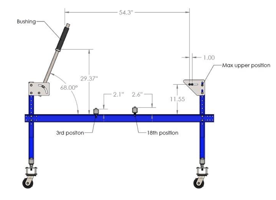
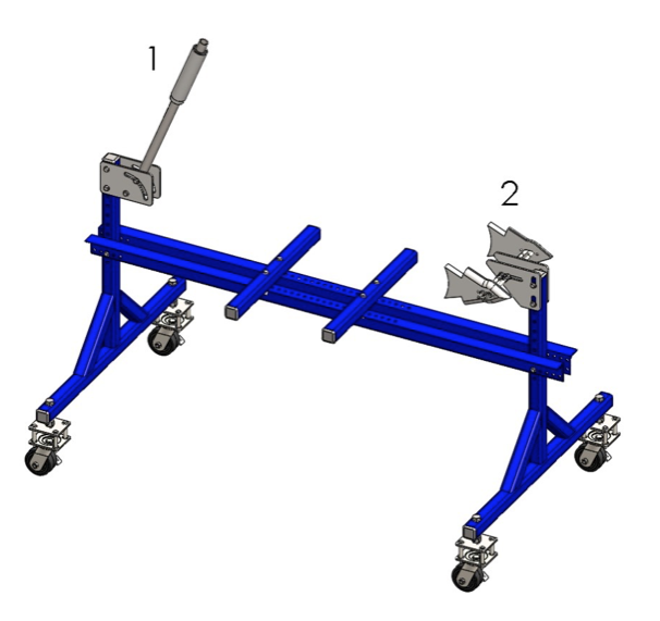
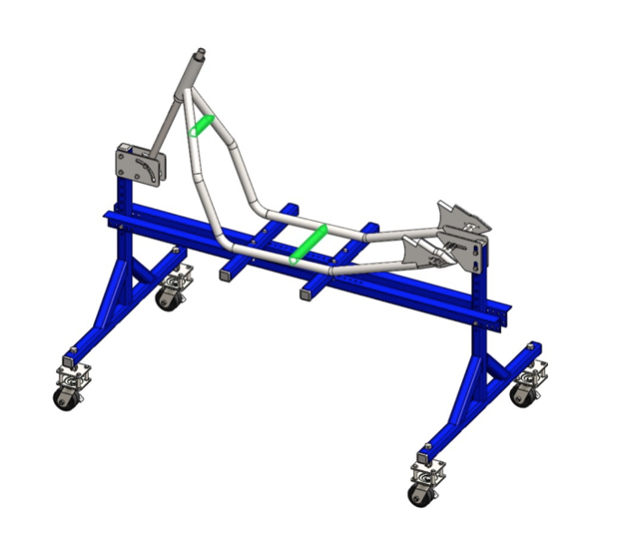
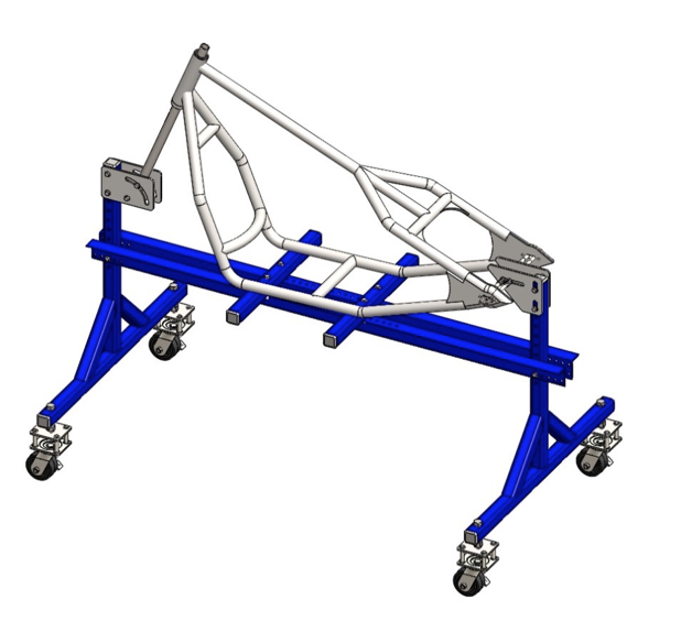
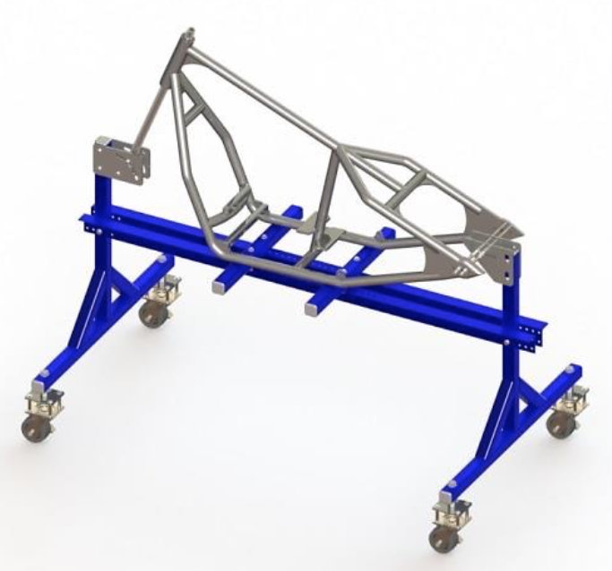
Step 1: Position the basic elements of the frame jig in proper position as shown on the figure. Move the elements in the specified position and tighten the bolts.
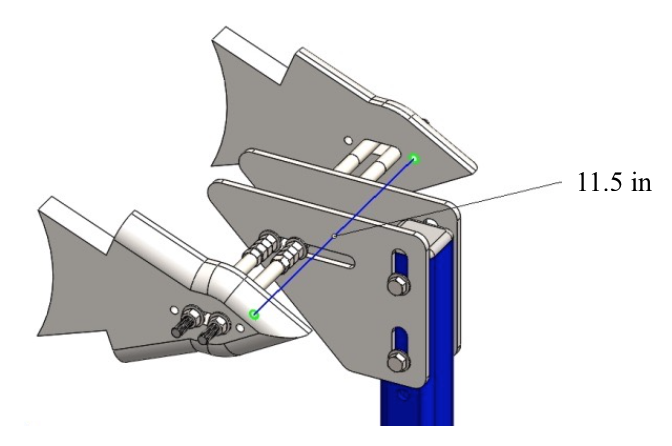
Step 2: Using the vertical slots of the rear axle mount plate perform the 11.55’’ dimension. Moving the threaded rod in horizontal slot perform the 54.3’’ dimension and then position the second rod 1’’ to the right. Tighten with nuts to ensure the position of the rods.
Step 3: Position the steering head shaft 68º measured from the longitudinal beam, so the steering head of the frame have to be with 22º rake (see drawing).
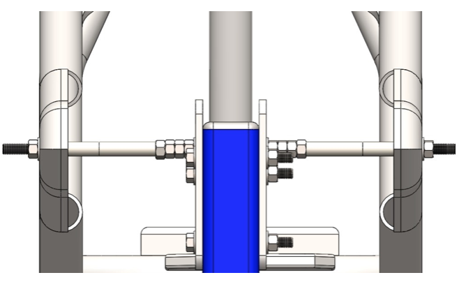
Step 4: Prepare bushing depending on dimensions of the used steering head. Position locking sleeve observing the drawing and lock it using the retaining splint. Thread the bushing as shown on the picture.
1. Assembling The Frame.
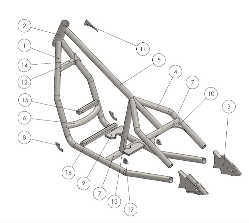
Rigid Bobber Frame Parts List:
- Down rails.
- Steering head.
- Axle plates.
- Left and right wishbone.
- Backbone.
- Curved brace bar.
- Straight cross bar.
- Front engine mount gusset.
- Rear mount gusset.
- Wishbone gusset.
- Steering head gusset.
- Steering down rail gusset.
- Center support.
- Small straight cross bar.
- Front engine mount block.
- Large front engine mount.
- Rear mounting gusset.
Step 1: Thread the steering head through (over) the bushing. The bushing is already mounted to the frame jig and the steering head tube has to be threaded through the bushing.
Mount the axle plates in their place on the frame jig. Use two threaded rods to ensure the horizontal position of the slots. You can use the two small holes to ensure the 11.5’’ size and fix the plates not movable.
Before proceeding to welding the frame check the major (and most important) dimensions shown on Fig.1.1.
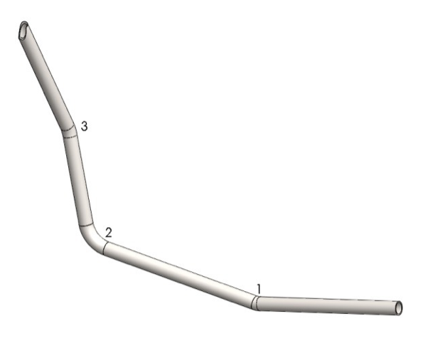
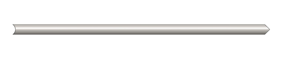
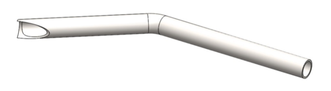
Step 2: Cut 70’’ long piece of 1.25’’ ERW tubing. Start bending the first bend observing the dimensions on the drawing. Execute the second and the third bend and check dimensions. Notch the end using a tube notcher. Repeat the steps for the second piece.
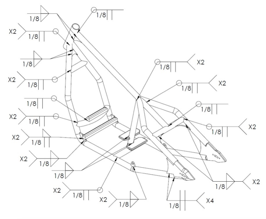
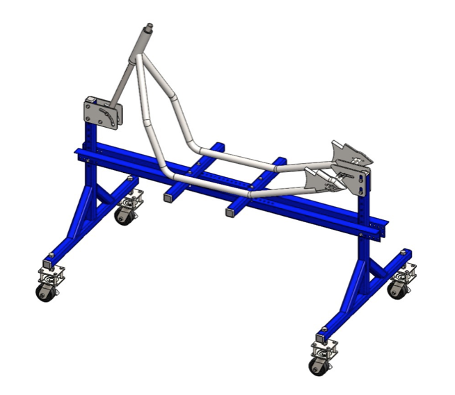
Step 3: Take one piece and align it as shown on the next picture. Tack weld in place. Proceed to second piece. Check dimensions and if there is no gaps complete the welds according to the welding plan (Fig. 2.1).
Step 4: Cut two pieces of 1.25’’ tubing, one 6’’ and one 12’’ long. Notch the ends and tack weld one of the bars to the bottom bar observing the dimensions on drawing. Weld the second piece between the down rails. Use welding fixtures if available for right positioning. Complete the welds according to the welding plan (Fig. 2.1).
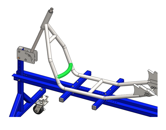
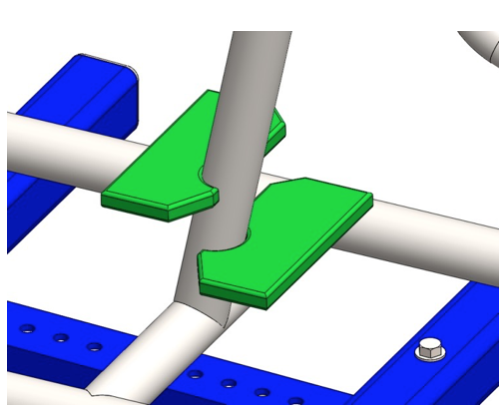
Step 5: Cut 12.5’’ long piece of 1.25’’ tubing. Bend the R11’’ radius observing the drawing. Notch the ends until you get the proper length. Tack weld between the down rails (colored in green). Complete the welds according to the welding plan (Fig. 2.1).
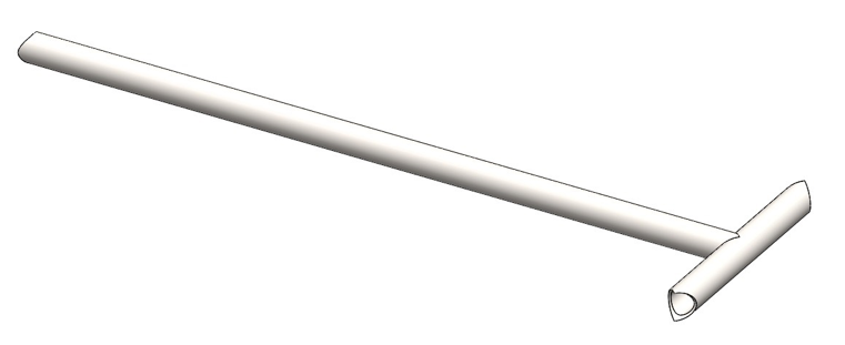
Step 6: Cut 40’’ long piece of 1.25’’ tubing. Notch the ends so they have to fit to the radius of the tubing and 90º each other rotated.
Step 7: Cut 12’’ long piece of 1.25’’ tubing. Notch the end using a tube notcher. Weld the backbone and cross bar together. The notches of the cross bar have to be parallel to backbone.
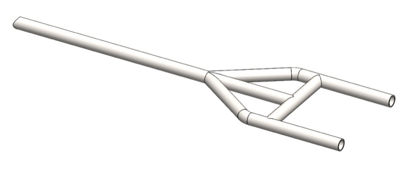
Step 8: Cut two 30’’ long pieces of 1.25’’ tubing. Execute the R2.0’’ bends observing the dimensions on the drawing. Notch the ends as shown on the next picture.
Position the two pieces and the assembly from Step 7 on a flat work surface. Tack weld them in place. Check alignment and dimensions and if there is no gaps complete the welds according to the welding plan (Fig. 2.1).
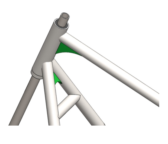
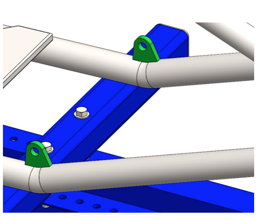
Step 9: Cut two 3x3’’ pieces of 0.25’’ thick mild steel sheet. Shape according to the drawing. Position them as shown on the next picture and complete the welds observing the welding plan (Fig. 2.1).
Step 10: Position the already made assembly as shown on the picture. Use welding fixtures if available for right positioning or hold the piece with one hand and tack weld with the other. Check alignment and if it meets the drawing complete the welds.
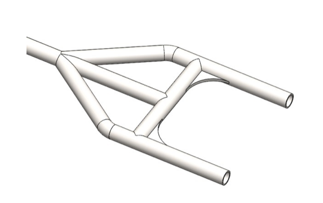
Step 11: Cut 22’’ or slightly longer piece of 1.25’’ tubing. Notch the ends until you get the proper length. Weld the notched tube between the backbone and the middle of the cross bar observing the welding plan (Fig. 2.1).
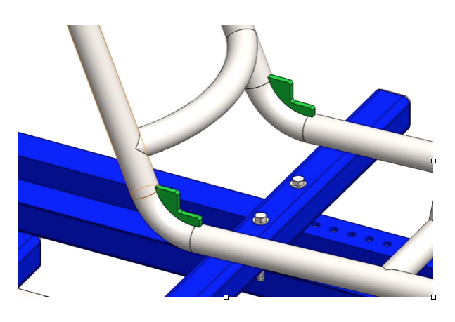
Step 12: Cut two pieces of 0.25’’ thick mild steel sheet. Shape observing the dimensions on the drawing. Position them as shown on the next picture and complete the welds according to the welding plan (Fig. 2.1).
Step 13: Cut two 2.5x2.5’’ pieces of 0.25’’ thick mild steel sheet. Shape the overall dimensions using an angle grinder. Position them to the frame using welding fixtures and complete the welds according to the welding plan (Fig. 2.1).
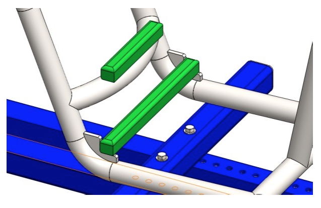
Step 14: Cut two pieces of 1 ¼’’ square bar, one 6’’ and one 12’’ long. Shape overall dimensions according to the drawing. Position them as shown on the next picture and complete the welds.
Step 15: Cut two 3x6’’ pieces of 0.25’’ thick mild steel sheet. Shape according to the drawing. Position them using welding fixtures or holding with one hand weld the first piece to the frame, and then proceed to the second piece. Complete the welds according to the welding plan (Fig. 2.1).
Step 16: Cut two pieces of 0.25’’ thick mild steel sheet. Shape the overall dimensions using an angle grinder and drill the holes. Position them to the frame using welding fixtures or use the holes for orientation. Complete the welds according to the welding plan (Fig. 2.1).
NOTE: The exact place of the gussets depends on the engine additive dimensions.
When all the steps are completed the welds must be finely filed to overflow with the tubes. Then proceed to custom painting the frame.
Congratulations!
You finished assembling the Rigid Bobber Frame!