Build An English Wheel!

You can build a homemade English Wheel following these assembly instructions.
It will be a top quality table top or regular English wheel which is bolted to a stand (bottom support).
You'll fabricate the bottom support from the plans and we show you how to do this as well.
You'll also need our plans for the English wheel to follow along.
Tools and Machinery Required:
1. Chop saw or Angle grinder.
2. Universal or CNC lathe (recommended).
3. Universal or CNC milling machine (recommended).
4. MIG, TIG or Arc Welding.
5. Bending machine.
6. Fitter’s vise.
7. Hammer, wrench set, tape measure, caliper.
8. Drill set – 0.5’’ - 2’’.
Materials Required:
1. Mild steel rectangular tube – 2’’ x 4’’ X 0.25’’ (17 ft); 2’’ x 2’’ X 0.25’’ (30 in).
2. Mild steel sheet – 15/16’’ thickness (5 in2); 1/4’’ thickness (17 ft2).
3.
7 ¾ ’’(8’’) round bar (4 in); 3 ¼ ’’ round bar (4 in); 1 ½ ’’ round bar
(11 in); 1 ¼ ’’ round bar (22 in); ¾ ’’ round bar (4 in); ½ ’’ round
bar (35 in).
4. Steel square bar – 1.5 x1.5 (36 in).
5. (8) BOLT HX-SHCS 0.5-20x1x1-S.
6. (1) BOLT HX-SHCS 0.375-16x0.5x0.5-S.
7. (1) BOLT 0.25-20x1.25x1.25-S.
8. (2) BOLT 0.75-10x3x1.75-S.
9. (8) SBHC Screw 0.375-16-0.5 HX-S.
10. (8) ALCNUT 0.5-20-N.
11. (2) ALCNUT 0.75-1-N.
12. (8) WASHER FW 0.5.
13. (2) WASHER FW 0.75.
14. (1) WASHER FW 1.125’’.
15. (1) WASHER FW 1’’.
16. (1) Retaining splint 0.075’’ X 1.5’’ (Safety pin).
17. (2) Ball bearing – SKF RLS92Z.
18. (2) Ball bearing – SKF RS5-2Z.
19. (4) Rubber pad 1x3x0.15.
1. English Wheel Frame Assembly.
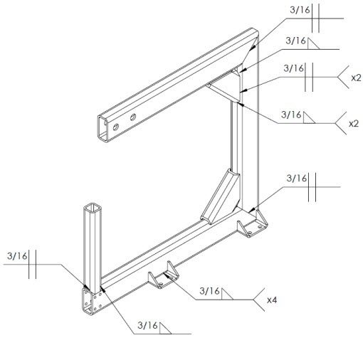 Fig. 1.1 Frame assembly welding plan.
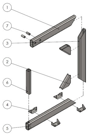 Fig. 1.2 Frame assembly montage plan.
English Wheel Frame Parts:
1. Upper beam (EW3.01.01.001).
2. Corner reinforcement (EW3.01.01.002).
3. Vertical beam (EW3.01.01.003).
4. Fixture (EW3.01.01.004).
5. Bottom beam (EW3.01.01.005).
6. Neck (EW3.01.01.006).
7. Bolt guide (EW3.01.01.007).
Step
1: Cut part number EW3.01.01.001 with the corresponding length and
shape the end at 45 degrees using an angle grinder. Drill the holes
observing the dimensions on drawing EW3.01.01.001.
Step 2: Cut
part numbers EW3.01.01.003 and EW3.01.01.005. Shape the ends at 45
degrees using an angle grinder and drill the holes of bottom beam.
Step
3: Cut part number EW3.01.01.002 (9 in work piece) and shape the ends
at 45 degrees using an angle grinder. See drawing EW3.01.01.002.
Step
4: Lay the parts out from Step 1, Step 2 and Step 3 on a flat work
surface. Position them observing the drawing EW3.01.01. Tack weld them
in place. Check alignment again and complete the welds according to the
welding plan (Fig. 1.1).
Step 5: Cut eight 2.5x7.5’’ work piece of 0.25’’ thick steel sheet ASTM 283. Bend profile observing the drawing.

Mill
the shapes and drill the holes according to drawing EW3.01.01.004, so
the form have to match the profile of rectangular tube. Take four of the
parts and position them observing the dimensions on drawing EW3.01.01.
Tack weld them in place. Check alignment again and complete the welds
according to the welding plan (Fig. 1.1).
Step 6: Cut part
number EW3.01.01.006 with the corresponding length and shape the end
using a milling machine. Complete the welds according to the welding
plan (Fig. 1.1).

Step 7: Mount the bolt guides at the holes of upper beam. See montage plan (Fig. 1.2).
2. Assembly Of The Big Wheel.
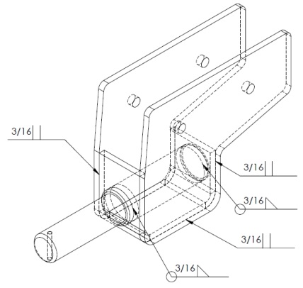 Fig. 2.1 Big wheel support welding plan.
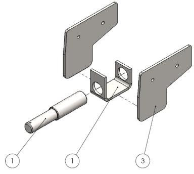 Fig. 2.2 Big wheel support montage plan.
Big Wheel Parts:
1. Big wheel shaft (EW3.01.02.001).
2. Support (EW3.01.02.002).
3. Side plate (EW3.01.02.009).
Step 1: Cut
2x8.2’’ work piece of 0.25’’ thick steel sheet ASTM 283. Bend the
profile observing drawing EW3.01.02.002. Drill the holes after bending,
so they will be concentric, otherwise you will not be able to thread the
shaft.
Step 2: Cut two 6x7.5’’ work pieces of 0.25’’ thick steel sheet ASTM 283. Mill the overall dimensions and drill the holes according to drawing EW3.01.02.003.
Step 3: Position the parts from Step 1 and Step 2 observing the montage plan (Fig. 2.2) and complete the welds.
Step
4: Cut 7.7’’ work piece of 1 ½’’ round bar. Turn it on a universal or
CNC Lathe according to dimensions on drawing EW3.01.02.001. Drill the
0.15’’ hole. Thread the part through the holes and complete the weld
according to the welding plan (Fig. 2.1).
3. Sliding Nut Assembly.
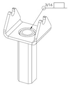 Fig. 3.1 Sliding nut welding plan.
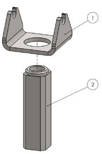 Fig. 3.2 Sliding nut montage plan.
Sliding Nut Parts:
1. Anvil wheel support (EW3.01.05.001).
2. Adjusting nut (EW3.01.05.002).
Step 1: Cut
work piece according to flat pattern on drawing EW3.01.05.001of 0.25’’
thick steel sheet ASTM 529. Drill the hole and bend the profile
observing drawing EW3.01.05.001.
Step 2: Cut 5.5’’ work piece of 1.5 x1.5 steel square bar ASTM 529. Drill the hole and turn the thread on universal or CNC Lathe. Turn the lowering according to dimensions on drawing EW3.01.05.002.
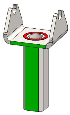
Step 3: Position the parts according to montage plan and complete the weld (Fig. 3.1). NOTE: The faces colored in green have to be parallel.
4. Adjusting Screw Assembly.
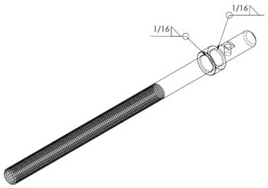 Fig. 4.1 Adjusting screw welding plan
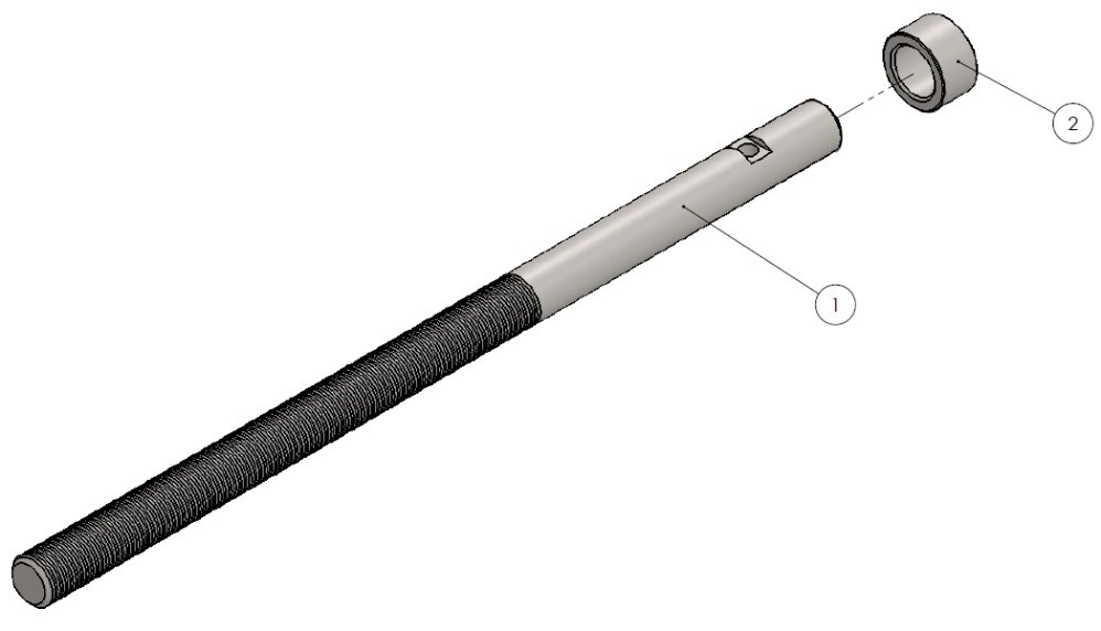 Fig. 4.2 Adjusting screw montage plan.
Adjusting Screw Parts:
1. Screw (EW3.01.06.001).
2. Ring (EW3.01.06.002).
Step 1: Cut
20’’ work piece of 1 ¼’’ round bar. Turn it on a universal or CNC Lathe
according to dimensions on drawing EW3.01.06.001. Mill the lowering and
tap the 3/8’’ thread.
Step 2: Cut 1’’ work piece of 1 ½’’ round bar. Turn it on a universal or CNC Lathe according to dimensions on drawing EW3.01.06.002. Check that you can thread the ring through the screw.
Step 3: Position the parts according to montage plan (see dimensions on drawing EW3.01.06) and complete the welds (Fig. 4.1).
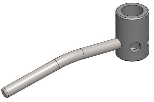
5. Handle Assembly.
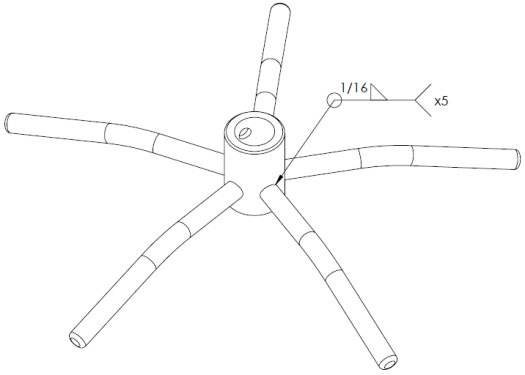 Fig. 5.1 Handle welding plan.
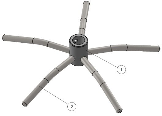 Fig. 5.2 Handle montage plan.
English Wheel Handle Parts:
1. Handle bushing (EW3.01.07.001).
2. Handle rod (EW3.01.07.002).
Step
1: Cut 2.5’’ work piece of 1 ½’’ round bar. Turn it on a universal or
CNC Lathe. Mill the lowering, drill the 0.345’’ and 5x0.5’’ holes
according to dimensions on drawing EW3.01.07.001.
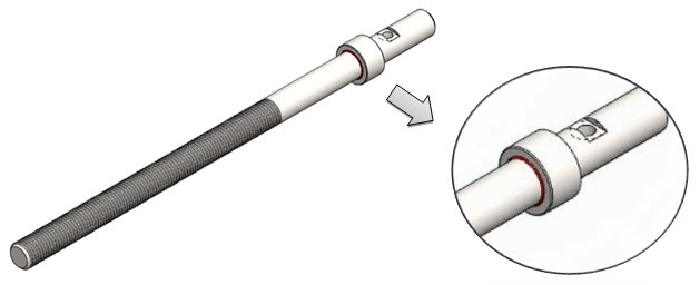
Step 2: Cut five 6.3’’ work pieces of ½’’ round bar. Bend observing the dimensions on drawing EW3.01.07.002.
Step 3: Put the handle bushing on a flat work surface and thread the handle rod through one of the five holes. Make sure the handle rod does not go beyond the hole. Complete the weld observing the welding plan (Fig. 5.1). NOTE: Keep clean the inner diameter, so you have to be able to thread the screw through the hole. Repeat the operations and mount all the handle rods.
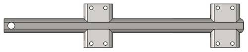
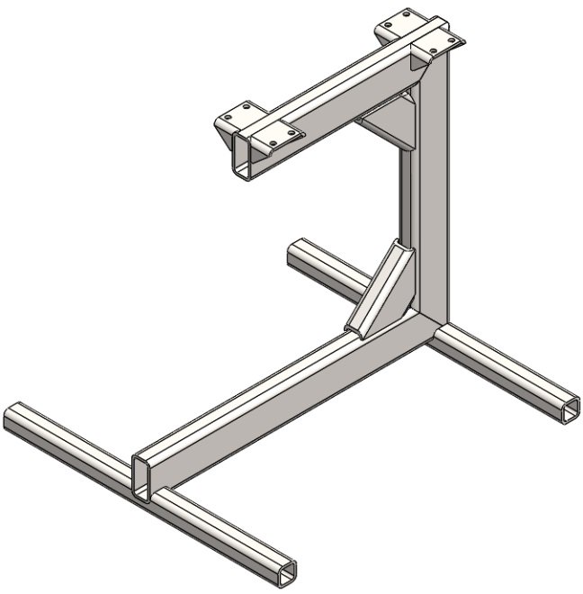
6. English Wheel Bottom Support Assembly.
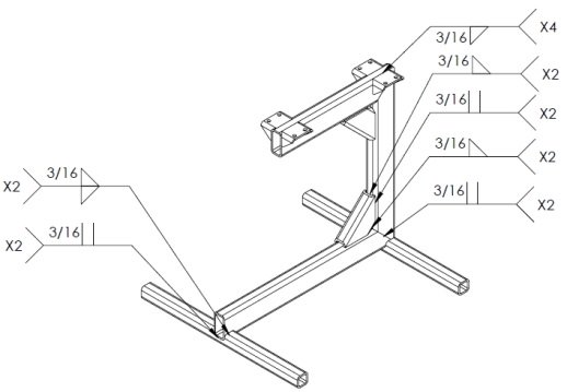 Fig. 6.1 Bottom support welding plan.
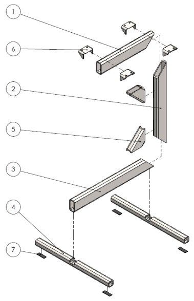 Fig. 6.2 Bottom support montage plan.
English Wheel Bottom Support Parts:
1. Upper element (EW3.02.01.001).
2. Vertical element (EW3.02.01.002).
3. Lower beam (EW3.02.01.003).
4. Leg (EW3.02.01.004).
5. Corner reinforcement (EW3.01.01.002).
6. Fixture (EW3.01.01.004).
7. Rubber pad (EW3.02.00.001).
Step
1: Cut part numbers EW3.02.02.001, EW3.01.01.002 and EW3.01.01.003 with
the corresponding length and shape the ends at 45 degrees using an
angle grinder.
Step 2: Cut part number EW3.01.01.002 (9 in
work piece) and shape the ends at 45 degrees using an angle grinder. See
drawing EW3.01.01.002.
Step 3: Lay the parts out from Step 1
and Step 2 on a flat work surface. Position them observing the drawing
EW3.02.01. Tack weld them in place. Check alignment again and complete
the welds according to the welding plan on Fig. 6.1.
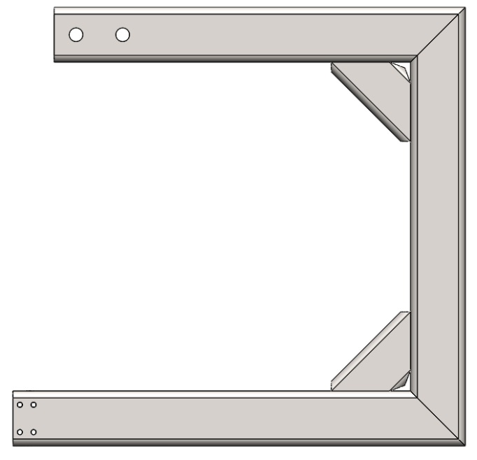
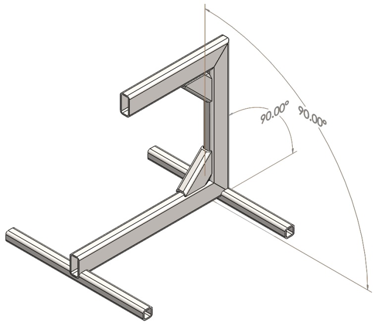
Step 4: Cut two pieces of part number EW3.02.01.004 and mill the lowering in the center as shown on the drawing. Position them observing the drawing EW3.02.01. Tack weld them in place. Check alignment on flat work surface, so the frame have to stay steady. Check the right angle as shown on the next picture. Complete the welds according to the welding plan on Fig. 6.1.
Step 5: Take four parts EW3.01.01.004 and
position them observing the dimensions on drawing EW3.02.01. Tack weld
them in place. Check the dimensions again and complete the welds
according to the welding plan (Fig. 6.1).
Step 6: Mount the rubber pads using a high strength glue.
8. Assembling The English Wheel.

Parts To Complete The English Wheel Assembly:
1. Bottom support (EW3.02).
2. Frame assembly (EW3.01).
3. BOLT HX-SHCS 0.5-20x1x1-S.
4. WASHER FW 0.5.
5. ALCNUT 0.5-20-N.
6. Sliding nut assembly (EW3.01.05).
7. Adjusting screw (EW3.01.06).
8. Brake (EW3.01.00.003).
9. Support (EW3.01.00.005).
10. Screw 0.375-16-0.5 HX-S.
11. BOLT 0.25-20x1.25x1.25-S.
12. Shim (EW3.01.00.004).
13. Handle (EW33.01.07).
14. BOLT HX-SHCS 0.375-16x0.5x0.5-S.
15. Ball bearing – SKF RS5-2Z.
16. Anvil shaft (EW3.01.04.002).
17. Anvil wheel (EW3.01.04.001).
18. Big wheel support (EW3.01.02).
19. BOLT 0.75-10x3x1.75-S.
20. WASHER FW 0.75.
21. ALCNUT 0.75-1-N.
22. Ball bearing – SKF RLS92Z.
23. Big wheel (EW3.01.03.001).
24. Shim (EW3.01.00.002).
25. Safety pin (EW3.01.00.001).
Before you start assembling the English Wheel there are a few parts that have to be manufactured or bought. They are not included in the assembly guide above, because they are separate parts not included in the units described. Their numbers from Fig. 7.1 are: 8, 9, 12, 24, 25,
Step 1: Position the Bottom support (1) and Frame assembly (2) as shown on Fig. 7.1 (or drawing EW3.00). The holes of the fixtures have to be concentric. Thread the bolts (3) and washers (4), tighten the nuts (5).
Step 2: Take the Sliding nut assembly (6) and Adjusting screw (7) and thread them through the two different sides of the neck (see Fig. 7.1). Turn the adjusting screw a few turns, so as to turn to the sliding nut.
Step 3: Position the Brake (8) over the ring of Adjusting screw (7) and tighten the bolt (11).
Step 4: Thread the support to the screw (see Fig. 7.1), lift up all the elements and tighten the screws (10).
Step 5: Thread the Shim (12) and Handle (13) to the screw and tighten the bolt (14). Now turn the handle and position sliding nut to the lowest level, so as not to interfere the next montage operations.
Step 6: Imbed the Ball bearings (15) to the Anvil wheel (17) and thread the shaft (16) through the ball bearings. Mount the anvil wheel assembly to the beds of sliding nut (6).
Step 7: Mount the Big wheel support (18) using the bolts (19), washers (20) and nuts (21) to the frame (2).
Step 8: Imbed the Ball bearings (22) to the Big wheel (23). Thread the assembly to the support shaft (18). Mount the Shim (24) and Safety pin (25).
Congratulations!
You built the English Wheel!
