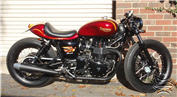
Soft Tail Sportster Frame Assembly Guide
This is a tutorial on how to build the Sportster Softail style frame which is available here. First we cover the tools and materials, then we go over the steps to building it using a frame jig. Enjoy!
Machinery and Tools Required:
- Frame jig (recommended).
- Chop saw or Angle grinder.
- Tubing bender.
- Tube notcher and tube notching accessories.
- MIG, TIG, or Arc Welding.
- Plasma cutter (recommended).
- Universal or CNC lathe (recommended).
- Fitter's vise.
- Hammer, wrench set, tape measure, caliper.
- Drill press.
- Drill set.
Materials Required:
- 1.25’’ ERW tubing (30 ft);
- Mild steel sheet – 1’’ thickness (150 in2);
- Mild steel sheet – 0.25’’ thickness (160 in2);
- 2’’ round bar (8 in);
- 1.25’’ round bar (20 in);
- (1) Steering head 8’’ tall;
- 1’’ x 1’’ block (13 in);
- (6) Clevis pin – 1/2 x 1.5’’;
- (6) Retaining splint –DIN 94– 3.2x18-C-St;
- (1) 12’’ Spring suspension rod;
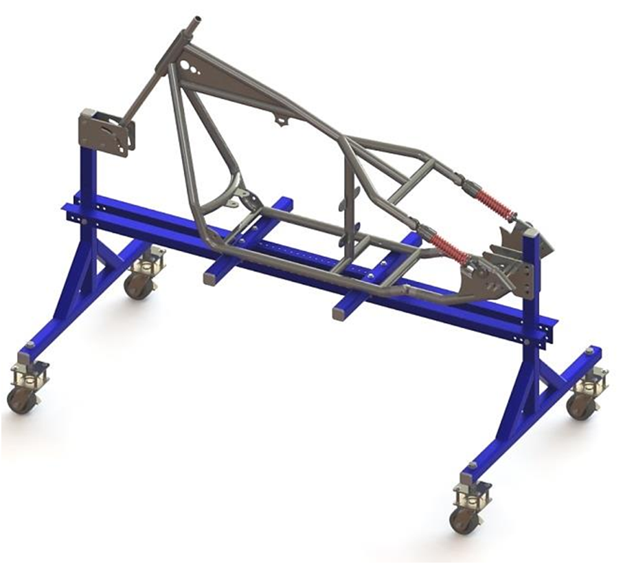
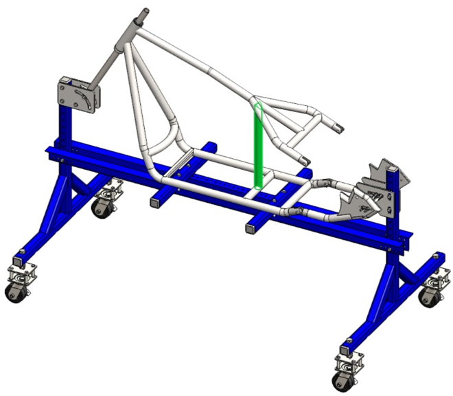
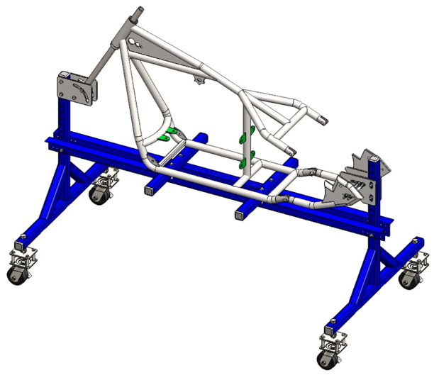
1. Preparing The Frame Jig For Your Frame Build:
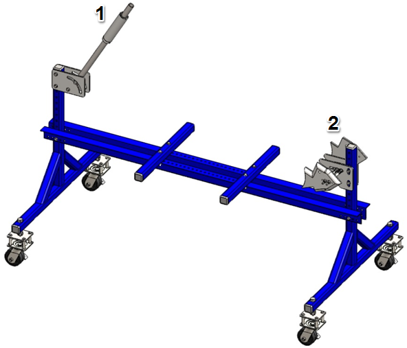
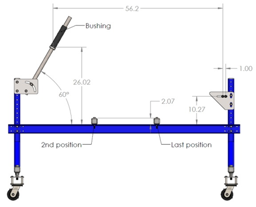 Fig. 1.1 Adjusting the frame jig
Step 1: Position the basic elements of the frame jig in proper position as shown on figure 1.1. Move the elements in the specified position and tighten the bolts.
Step 2: Using the vertical slots of the rear axle mount plate perform the 10.27’’ dimension. Moving the threaded rod in horizontal slot perform the 56.2’’ dimension and then position the second rod 1’’ to the right. Tighten with nuts to ensure the position of the rods.
Step 3: Position the steering head shaft 60º measured from the longitudinal beam, so the steering head of the frame have to be with 30º rake (see drawing).
Step 4: Machine bushing depending on dimensions of the used steering head. Position locking sleeve observing the dimensions on Fig. 1.1 and lock it using the retaining splint. Thread the bushing as shown on the picture.
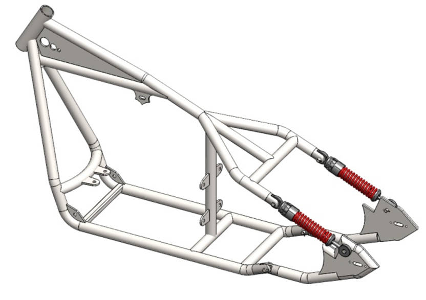
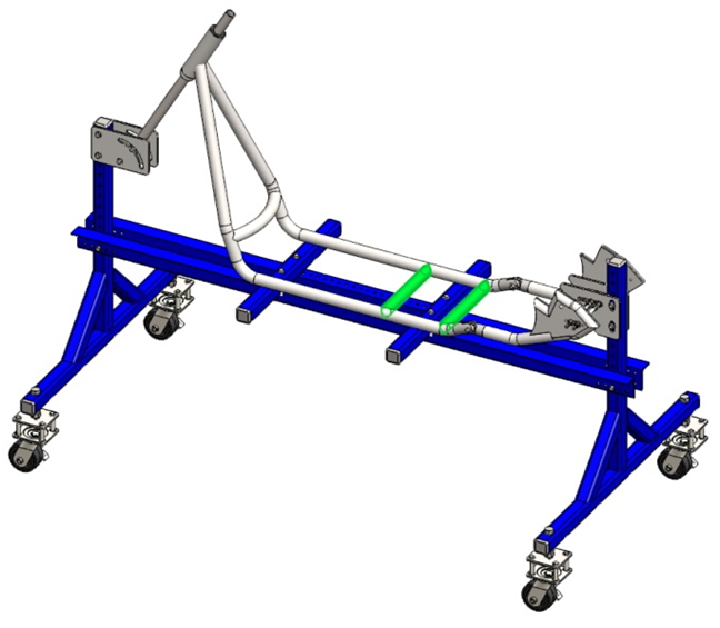
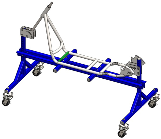
2. Assembling The Frame:
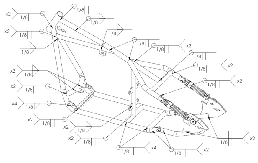 Fig. 2.1 Frame assembly welding plan Fig. 2.1 Frame assembly welding plan |
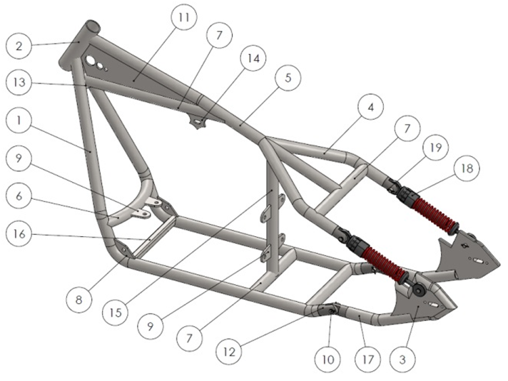 Fig. 2.2 Frame assembly montage plan Fig. 2.2 Frame assembly montage plan |
Parts:
- Down rails.
- Steering head.
- Axle plates.
- Left and right wishbone.
- Backbone.
- Curved brace bar.
- Straight cross bar.
- Front engine mount gusset.
- Eyelet mount gusset.
- Clevis pin.
- Steering head gusset.
- Soft tail hinge.
- Steering head gusset.
- Top center engine mount.
- Center support.
- Large front engine mount.
- Rear axle bar.
- Suspension spring.
- Retaining splint.
Step 1: Thread the steering head through the already mounted to the frame jig bushing.
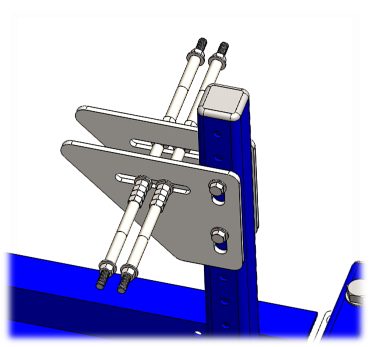
Mount the axle plates in their place on the frame jig. Use two threaded rods to ensure the horizontal position of the slots. You can use the two small holes to ensure the 11.5’’ size and fix the plates not movable.
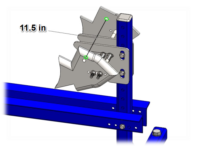
Before proceeding to welding the frame check the major (and most important) dimensions shown on Fig. 1.1.
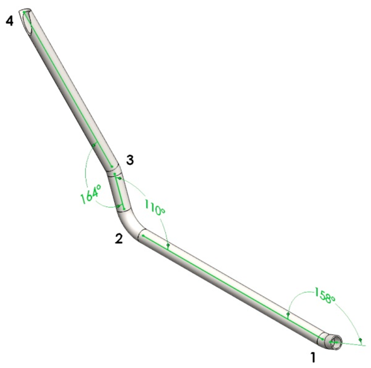
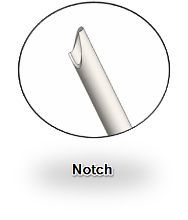
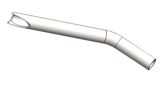
Step 2: Cut 70’’ long piece of 1.25’’ ERW tubing. Start bending the first 158º bend observing the dimensions on the drawing. Execute the second 110º and the third 164º bend. Check the final dimensions. Notch the end using a tube notcher. Repeat the steps for the second piece.
 |
 |
Step 3: Take already bended down rails and align them as shown on the next picture using welding fixtures. Tack weld them to the steering head.
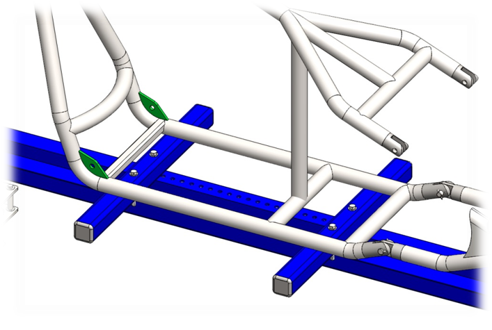
Step 4: Cut four 3’’ long pieces of 1.25’’ round bar. Machine the parts accordingly to the drawing. Take two pieces and tack weld them to the down rails as shown on the next picture. Make sure the slots are parallel to axle plates.
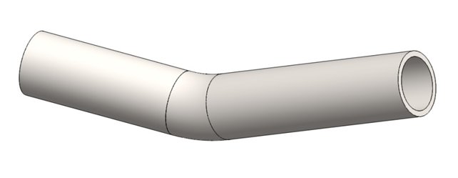
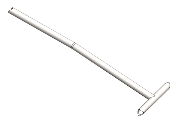
Step 5: Cut at least 13’’ long pieces of 1.25’’ tubing. Bend according to the drawing. Leave the longer side a bit longer.
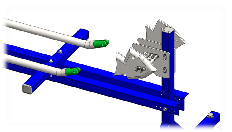
Step 6: Cut two 3’’ long pieces of 1.25’’ round bar. Machine the parts according to the drawing. Tack weld them to the rear axle bars. Make sure the slots are parallel to the bending.

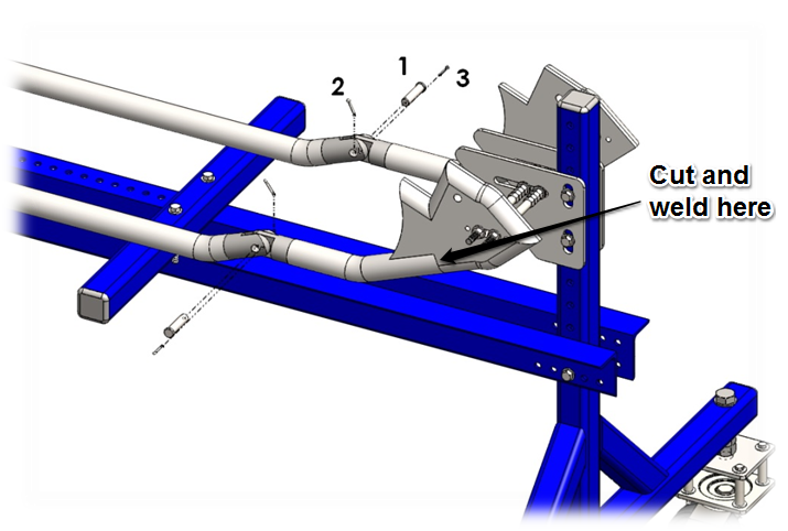
Step 7: Position the holes of the hinges concentric and thread the clevis pin (1). Thread the retaining splint through the holes of the clevis pin (2). Lock the hinge using locking pin during maintenance and assembly of the frame (3). Cut the proper length and tack weld the axle bars to the axle plates.
Step 8: Cut 13’’ long piece of 1.25’’ tubing. Bend the R12’’ radius observing the drawing. Notch the ends until you get the proper length. Tack weld between the down rails.
Step 9: Cut two 12’’ long pieces of 1.25’’ tubing. Notch the ends using a tube notcher. Tack weld the cross bars between the down rails.
Step 10: Check alignment of all elements and if it meets the drawing dimensions complete the welds according to the welding plan (Fig. 2.1).
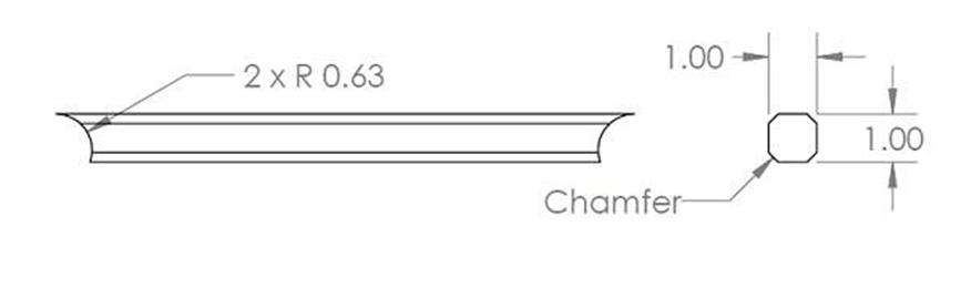
Step 11: Cut 13’’ long piece of 1’’ x 1’’ block. Machine the chambers and the radiuses. Weld the machined bar between the down rails observing to the welding plan.
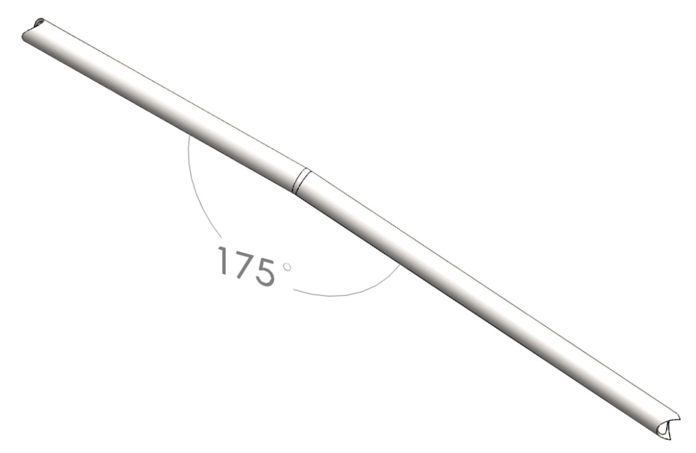
Step 12: Cut 39.5’’ long piece of 1.25’’ tubing. Bend according to dimensions on the drawing. Notch the ends so they have to fit to the radius of the tubing and 90º each other rotated.
Step 13: Cut 14’’ long piece of 1.25’’ tubing. Notch the end using a tube notcher. Weld the backbone and cross bar together. The notches of the cross bar have to be parallel to backbone.
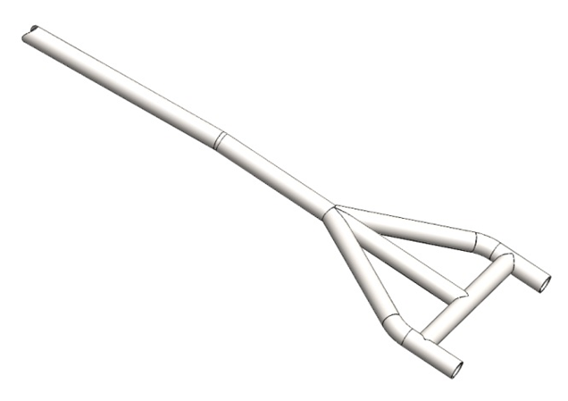
Step 14: Cut two 18’’ long pieces of 1.25’’ tubing. Execute the R3.0’’ bends observing the dimensions on the drawing. Notch the ends as shown on the next picture.
Position the two pieces and the assembly from Step 13 on a flat work surface. Tack weld them in place. Check alignment and dimensions and if there is no gaps complete the welds according to the welding plan (Fig. 2.1).
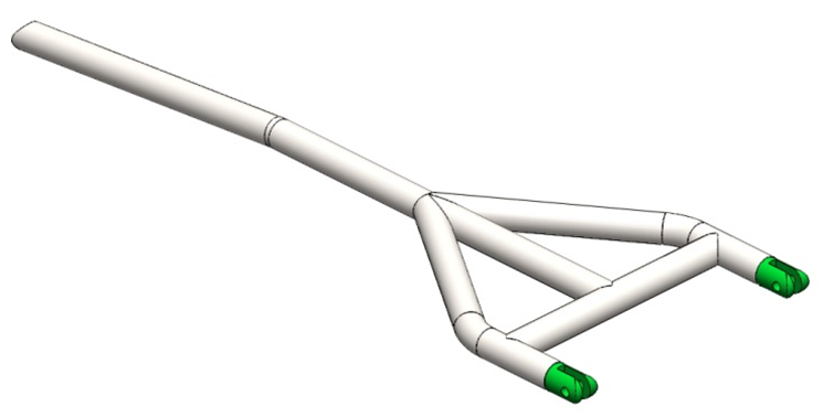
Step 15: Take the already machined hinges from Step 6. Position them as shown on the next picture and complete the welds observing the welding plan (Fig. 2.1).
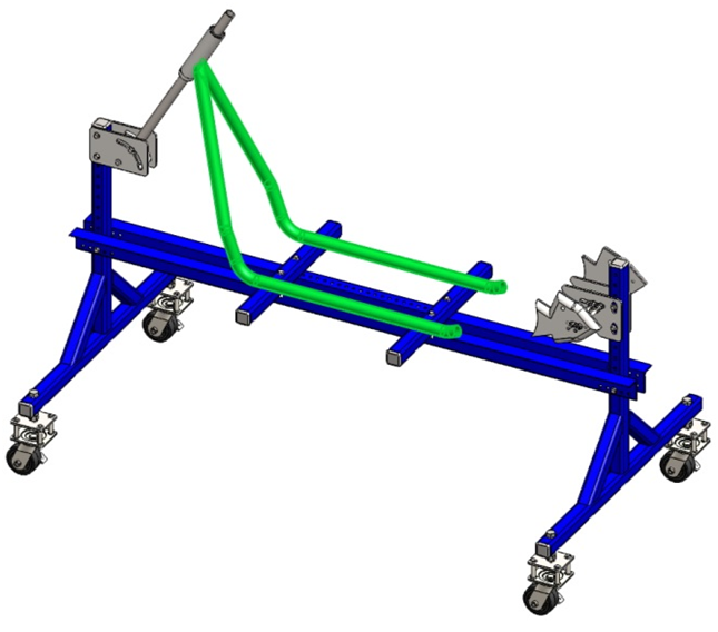
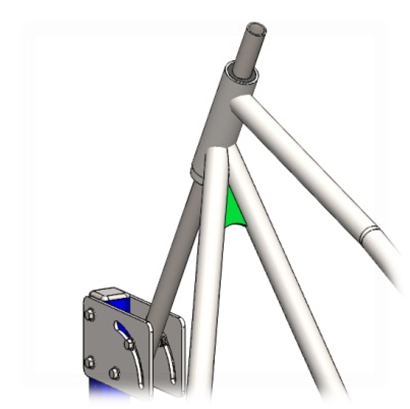
Step 16: Cut 18.5’’ long piece of 1.25’’ tubing. Notch the ends with angles matching the angles between the tubing (see main drawing). Tack weld the notched tube to the cross bar. Ensure it's in upright position. Position the already made assembly from previous steps as shown on the picture. Use welding fixtures if available for right positioning or hold the piece with one hand and tack weld with the other hand. Check alignment and if it meets the drawing dimensions complete the welds according to the welding plan (Fig. 2.1).
Step 17: Cut 3.5x2.5’’ piece of 0.25’’ thick mild steel sheet. Shape observing the dimensions on the drawing. Weld between the down rails.
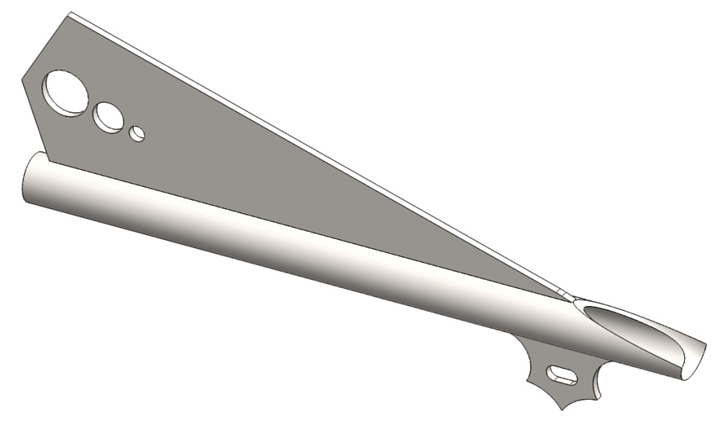
Step 18: Cut 5.5x20’’ piece of 0.25’’ thick mild steel sheet. Shape the overall dimensions using an angle grinder and drill the holes (the holes on the plate are for aesthetics).
Cut 2.5x4.5’’ piece of 0.25’’ thick mild steel sheet. Shape the overall dimensions and mill the lot.
NOTE: It's recommended to use a plasma cutter for one step machining the parts.
Cut 22’’ piece of 1.25’’ tubing. Notch the end as shown on the next picture and proceed to welding the pieces according to the welding plan.
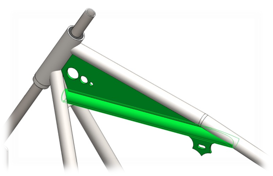
Step 19: Proceed to welding the assembly from Step 18 to the frame. See welding plans.
Step 20: Cut two 1.5x4.5’’ pieces of 0.25’’ thick mild steel sheet. Machine the overall dimensions using an angle grinder or plasma cutter. Drill the holes. Position the gussets on the frame using welding fixtures and complete the welds according to the welding plan (Fig. 2.1).
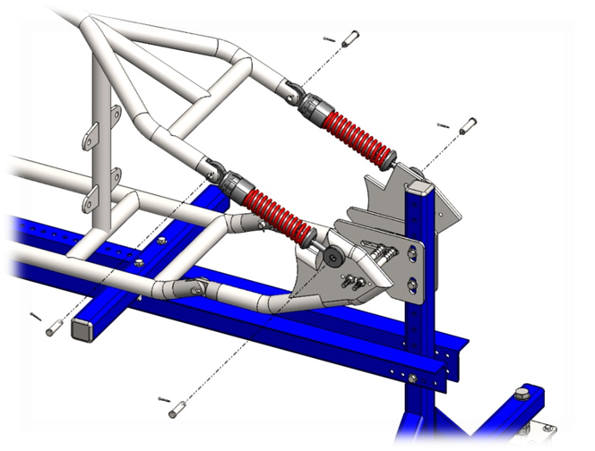
Step 21: Cut six 2.5x2.5’’ pieces of 0.25’’ thick mild steel sheet. Shape the overall dimensions using an angle grinder or plasma cutter and drill the holes. Start tack welding the pieces to the frame. (NOTE: The position of the gussets depends on the engine additive dimensions). Check alignment and complete the welds according to the welding plan (Fig. 2.1).
Step 22: roceed to mounting the spring suspension rods to the frame. Position the hole of the left ring concentric to the hinge. Thread the clevis pin through the holes and lock using retaining splint. Lift up the other side of the part and position the hole of the right ring concentric to the hole on the axle plate. Thread the clevis pin through the holes and lock using retaining splint. Repeat the step for the second spring rod.
Step 23: Remove the locking pins from the lower hinges. Use these locking holes during future maintenance.
When all the step are completed the welds must be finely filed to overflow with the tubes. Then proceed to custom painting the frame.
You finished assembling the Soft Tail Sportster Frame!